1. Gantry Crane Introduction
This manual is applicable for installation, maintenance of gantry crane and can be used by installation worker, operator, maintainer.
1.1 Gantry crane main forms and uses
The design and fabrication of General purpose gantry crane (hereinafter referred to as: crane) follows the national and industrial standard GB/T3811 Crane Design Regulations, GB/T14406 General Purpose Gantry Crane, etc. the crane works in open air or indoor, and its spreader is hook, grab or electromagnetic chuck (electromagnet) , or use two or three kinds of them at the same time.
According to the structure forms of main girder, gantry crane can be divided into single-girder and double-girder. Single-girder gantry crane, according to its leg shapes, is divided into L-type and C-type. Double-girder gantry crane, according to its gantry shapes, is divided into A-type and U-type. There are three kinds of gantry structures: double cantilevers, single cantilever and no cantilever. Semi-gantry crane is just having legs at one side. Trolley forms: one trolley and two trolleys which can work separately or together. Truss gantry crane with small wind area is mainly used in the outdoor with higher wind pressure.
When the spreader is hook, working duty is A3~A7. when the spreader is grab or electromagnetic chuck, working duty is A4~A8.
1.2. Gantry crane operating environment
1.2.1 Crane power supply is 380v, 3-ph, 50Hz. Voltage fluctuation in motor and electrical equipment is: upper limit +10% of, rated voltage range. Lower limit -15% of, rated voltage range. Crane inside voltage loss should conform with the standard GB 3811.
1.2.2 Installation of crane rails should conform to the standard GB 10183.
1.2.3 The altitude of crane operating place should be less than 1000m, if it's higher, indicate it in the contract.
1.2.4 operational environment has no flammable, explosive and corrosive gas.
1.2.5 The radiant temperature of the crane hook caused by lifting objects must be less than 300℃.
1.2.6 The Max. Wind pressure for Crane used outside under non-operational condition is 800P(equal to 11 degree wind).
1.2.7 Climatic condition of crane normal operation (if higher than these conditions, specify it when placing the order).
1.2.7.1 Gantry crane used indoor
① Ambient temperature ≤ +40℃, average temperature during 24 hours ≤+35℃.
② Ambient temperature ≥-5℃.
③ Temperature is +40℃, relative humidity shall be no more than 50%.
1.2.7.2 Gantry crane used outdoor
① Environmental temperature ≤+40℃, average temperature during 24 hours ≤+35℃.
② Environmental temperature ≥-20℃.
③ Environmental temperature ≤+20℃, relative humidity is allowed to reach l00% temporarily.
④ Working wind pressure shall be no more than: inland 150Pa (equal to 6 degree wind), inshore 250Pa (equal to 7 degree wind ).
1.3 Performance parameter
Gantry crane specifications are the index that shows crane operational capacity. Its main specifications: capacity, lifting height, span, working duty, working speed, details see the drawings. The maintenance of its components (such like: reducer, motor, brake, etc.) refers to attached instructions.
1.4 Compositions of Gantry crane
Crane is composed of gantry steel structure, trolley, crane traveling system, electrical system, etc. Crane that works outdoor should be equipped with the following safety devices: rail clamp, load limiter, limit switch of each mechanism, and safety protections specified in crane safety regulations. According to requirements, anchor device, tie-down wind speed / anemoscope, deviation-rectifying device shall be set.
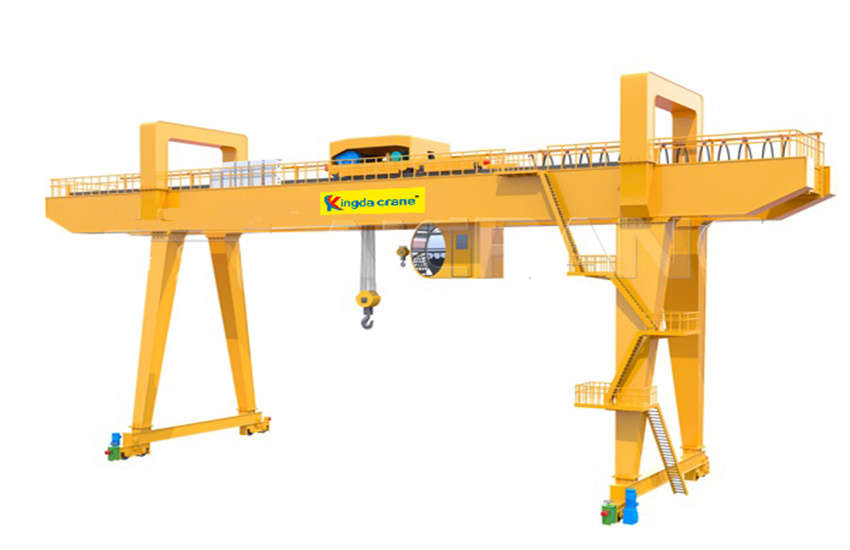
Sketch 1. 3D drawing of A-shape double-girder gantry crane
1.4.1 Gantry
Gantry is composed of main girders, legs (apply rigidity leg and flexibility leg when the span is long ) , lower crossbeam, end carriage, saddle (without it if no cantilever ) , trolley traveling rails, etc. use high strength bolts to connect all of the above together.
1.4.1.1 Main girder
1.4.1.1.1 Main girder is of box or truss shape.
1.4.1.1.2 Main girder shall be equipped with walk-way and handrails which is easy for maintenance and inspection.
1.4.1.1.3 Taking the camber into consideration when designing the main girder, the camber shall be no less than the national standard GB/T14406-2011 General-purpose Gantry Crane and other relevant standards.
1.4. 1. 2 Legs
By adopt welded-box or truss structure, the leg is composed of upper and lower flanges, steel plates or profile steel. Upper flanges are big and lower flanges are small, so the leg's section from the upper to the lower is different. This structure can carry vertical and load horizontal effectively.
1.4.1.3 Lower crossbeam, end carriage, saddle
Adopt welded box or truss structure. The upper flanges of lower crossbeam connect with the legs, and the lower flanges of lower crossbeam connect with the crane. End carriages connect with main girders through the flanges. Saddle connects the upper main girder through the flanges on both sides.
1.4.1.4 Cabin
The structure of cabin is composed of steel plates and profile steel. The cabin is fixed on the support under main girder. Its connecting method is solid and reliable with enough rigidity and strength. The arrangement inside cabin should follow the national standard, to embody the humanity and meet the client's requirements.
1.4.1.5 Platform, ladder
There will be reliable ladder in the places that need operation, inspection and maintenance; moreover, there will be enough space in these places. Height of the handrails on the platform is 1050mm. Walking way and platform should take anti-skid measures.
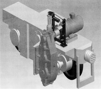
1.4.2 Gantry crane traveling system
Crane traveling mechanism adopts respective driving mode. Crane traveling system is composed of motor, brake, reducer, wheels, drive shaft, coupling, etc.
Working principle: after turning on the power, the brake opens, the motor output the power, the reducer changes the speed, then drive shaft and coupling drive the wheels and make crane move forward and backward. After turning off the power, the brake closes and the crane stops.
Crane have 4 or 8 wheels (some more particularly ) , wheel and the angle bearing box with rolling bearing (or 45° structural bearing box ) are assembled and installed on end carriage or balance bogie.
Sketch 2 crane traveling system 3D drawing with bogie.
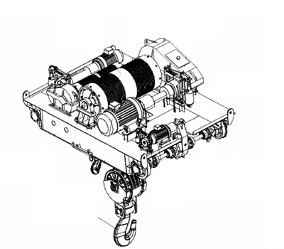
1.4.3 Gantry crane trolley
The trolley is composed of one set or two sets of (main, Aux. lifting ) lifting mechanisms, cross travel mechanism, trolley frame, etc.
1.4.3.1 lifting mechanism
Each lifting system is composed of motor, brake, reducer, drums, wire rope, hooks, drive shaft, coupling, etc. Working Principle: after turning on the power, the brake opens, the motor out puts the power, the reducer changes the speed, then transmission shaft and coupling drive the drum, the hook will go up and down with winding of wire rope. When turning off power, the brake closes, and the hook stops working and keeps the objects suspended in the air.
1.4.3.2 Cross travel system
Cross travel system adopts centralized (or separate ) drive and is composed of motor, brake reducer, wheels, drive shaft, coupling, etc.
Working principle: after turning on the power, the brake opens, the motor outputs the power, the reducer changes the speed, then drive shaft and coupling drive the wheel and make crane move forward and backward. After turning off the power, the brake closes and the trolley stop working.
The trolley has 4 or 8 wheels (some more particularly ) . wheel and the anlgle bearing box (or 45° structural bearing box with rolling bearing ) are assembled and installed on end carriage of the trolley.
Sketch 3 Drawing of the trolley.
1.4.4 Gantry crane electrical control system
1.4.4.1 Power supply and distribution system
1.4.4.1.1 Power supply
Power supply is 3 phase, 4 wires (3p+PE ) , 380v, 50Hz. Power is conducted by bus bar or cable drum to power distributing cabinet, then lead to other power source, such as the power illumination, auxiliary circuit, and so on.
Equip one separate illuminating transformer that supplies 220v, 36v power supply for lighting, maintenance socket and auxiliary circuit, and transformer's main end and Aux. End have breaker protection.
With Special connecting line PE, and all of electrical equipment have special line that connects with PE line to form power grid. Crane itself is not to be taken as ground loop.
Voltage degree as follows:
| Power supply |
3-ph, 4wire |
AC |
380V±10% |
50HZ |
| Power circuit |
3-ph |
AC |
380V |
50HZ |
| Illuminating power |
|
AC |
220v |
50HZ |
| Control power |
|
AC |
380v |
50HZ |
| Power socket |
|
AC |
220v |
50HZ |
|
AC |
36v |
50HZ |
1.4.4.1.2 Power supply of crane and trolley
Gantry crane: cable drum or bus bar
Trolley: movable cable pulley
1.4.4.2 Gantry crane Distribution system
1.4.4.2.1 Distribution system is composed of general breaker, general power contact and over current protection, which ensures that sub-circuit can be repaired individually without affecting other sub-circuit, so the affection of failure will be reduced in a small scope. Distribution control loop is equipped with whole power's start, stop, emergency switch, power indicator, safety switch, emergency limit, short circuit, over current and loss voltage protection, etc. the general circuit disconnects automatically as the power is off. Each system is equipped with zero protection (that the general break automatically, when the power is off. If control pendent is not in zero position, all of the system can not be started automatically. ) After failure recovery, all mechanisms can't start automatically if the control pendent doesn't return to zero.
1.4.4.2.2 Illuminating transformer supply the power to bridge lighting, indoor lighting, electric bell and alarming light, power socket and illuminating control circuit. Crane distribution cabinet is equipped with maintenance socket with 220v, 36v.
1.4.4.2.3 The cabin is equipped with foot switch and operator can use foot switch to send out alarming signal.
1.4.4.2.4
the meaning of item code:
| =01 |
power distribution protection |
| =02 |
illumination signals |
| =05 |
main lifting mechanism |
| =06 |
Aux.lifting mechanism |
| =10 |
Cross travel mechanism |
| =12 |
Long travel mechanism |
1.4.4.3 Gantry crane main (Aux.) lifting system
Control methods of Lifting system: series resistance, frequency control, stator voltage regulating, and Adopt series-resistance speed control otherwise specified
1.4.4.3.1 Series resistance has two methods: cam controller and contactor cutting resistance control.
Cam controller is used for cabin operation with the motor power ≤26KW. Adopt AC380V KT type cam controller with 5 speed and RT type resistance together with sectional cutting resistance to control motor's start current and realize stable starting.
Contactor series resistance control uses LK type command controller, conversing contactor cutting resistance contactor, time relay and rotor resistance together to meet the different speed requirements during lifting. Details refer the attached drawings.
1.4.4.3.2 Frequency inverter speed control
Lower voltage breaker, contactor and inverter compose of control loop and drive frequency motor, then motor's incremental encoder feedback speed changes and reach speed closed loop control. Detailed control methods see the attached drawings.
1.4.4.3.3 Stator variable voltage speed control method
The control circuit, composed of low voltage breaker, stator voltage regulator and rotor resistance, can drive the lifting motor and control the stator voltage of motor by adjusting the thyristor conducting angle as well as change the mechanical performance by changing the stator resistance of the motor. Detailed control methods refer to the attached drawing.
1.4.4.4 Gantry crane and trolley traveling system
1.4.4.4.1 Series resistance has two methods: cam controller and contactor cutting resistance control.
Cam controller is used for cabin control with the motor power ≤ 26KW and control method is cabin. Adopt AC380V type cam controller with 5 blocks and RT type resistance with sectional cutting resistance to control motor's start current and realize stable starting.
Contactor series resistance control uses LK type command controller, conversing contactor, cutting resistance contactor, time relay and rotor resistance together to meet the different speed requirements during lifting. Detailed methods see the attached drawings.
1.4.4.4.2 Variable frequency speed control method
The control circuit, composed of low voltage breaker, contactor and frequency inverter, can drive the frequency motor to realize the V/F open loop speed control and custom speed control. The acceleration/deceleration time setting of custom start or stop can make the mechanism move stably, reliably and precisely. Use the brake unit and brake resistance of inverter to release the energy caused during motor falling. Detailed control methods refer to the attached drawing.
1.4.4.4.3 Stator variable voltage speed control method
The control circuit, composed of low voltage breaker, stator voltage regulator and rotor resistance, can drive the traveling motor and control the stator voltage of motor by adjusting the thyristor conducting angle as well as change the mechanical performance by changing the stator resistance of the motor. Detailed control methods refer to the attached drawing.
1.4.5 Gantry crane electric control system consists of the followings main parts:
| Power distribution comprehensive protection cabinet |
| Main lifting control cabinet |
motor |
brake |
resistor |
| Aux. lifting control cabinet |
motor |
brake |
resistor |
| Long travel control cabinet |
motor |
brake |
resistor |
| Cross travel control cabinet |
motor |
brake |
resistor |
| Lighting transformer |
| The controller of each mechanism may install independently or centralized control. |
| Lighting signal and safety protection device |
| Conductive device of trolley cable |
| Main electrical components such as breaker,contactor and relay use domestic well-known products. |
1.4.6 Gantry crane operation
All mechanisms operated by cam controller of the cab or master controller, control the lifting and running of crane and trolley. The cab has emergency stop button which can cut off the entire power when pressing the button in the case of emergency.
1.4.7 Gantry crane protection and Indication
The crane has emergency switch power which can cut off the general power in the case of emergency. The switch is located in the distribution cabinet.
- 1.4.7.1 The motor is equipped with full functional protections which can protect failure such as over current short circuit of motor effectively.
- 1.4.7.2 The crane has zero protection. When the mechanisms are ready to run or power restoration, firstly the controller must be placed at zero, the motors of each mechanism can start when pressing the button.
- 1.4.7.3 Each handrail gate has safety electrical interlock.
- 1.4.7.4 The crane has warning bell which may carry out working signal by pedal switch.
- 1.4.7.5 overload limiter: The crane has overload limiter. The indicator will automatically make alarming when the load reaches 90% of the rated load;the crane can automatically cut off the power of lifting mechanism when the load reaches 105% of the rated load.
- 1.4.7.6 Protection device at the rising limit position: The lifting mechanism of hook has limit device. It can automatically cut off power when arriving at the limit position.
- 1.4.7.7 Stroke limiter: The both sides of crane and trolley travelling mechanism are equipped with stroke limiter which can automatically cut off power when crane and trolley travel to the limit position, but they can run in the other direction.
- 1.4.7.8 The crane has voltage-loss and zero protection, the driver can cut off the power in the convenient position.
- 1.4.7.9 The cab and the gate on the bridge have electrical interlock protection devices.
- 1.4.7.10 There is sound and light alarm lamp of crane travelling, emergency stop button box and crane rail clamp on the crane leg.
- 1.4.7.11 When lifting height above rail is over 30m, the top should be equip with anemometer and aviation obstruction light.
- 1.4.7.12 When the crane is used in the field, without supertall buildings, it has lightning protection.
2. Gantry Crane Installation and Commissioning
2.1. Gantry crane installation preparations and precautions
- 2.1.1 Before the erection, erection persons with the deputies from Erection Company and Manufacturer should open the box to check the number of components and spare parts that listed on the packing list and attached documents, to see if there is any shortage or damage.
- 2.1.2 Accidents such as twist, bending or striking should be especially avoided while unloading or transporting. When lifting the crane, two lifting points are necessary and there must be underlay in the enlacing point, and the enlacing points are at both ends of the structures as soon as possible.
- 2.1.3 Transportation of crane should adopt lengthened truck or flat trailer. Dragging on ground or rollers is forbidden.
- 2.1.4 If storing, crane should be flatly and stably placed on sleepers. The sleepers must be placed symmetrically and the ground must be massy in order to prevent any transfiguration of the bridge.
- 1.5 If storing for long time outdoor, waterproof measures should be taken. Necessary measures should be taken for transmission parts and electric equipments to avoid water, rust, erosion, bump and theft.
- 2.1.6 Before the erection, the appearance of all machine parts and metal structures should be checked carefully for damage and observe the peeling of paint coating and the rusting of machine
- parts. According to results of the appearance check, compared with the technical requirements of the erection drawing and related technical documents, carefully study the erection proposal and erection procedures.
- 2.1.7 The defects caused by the improper handling and unsuitable storage and the parts which exceed stipulation error should be adjusted in according with the technical requirements. If there is any transfiguration of the metal structure, it must be adjusted before erection. If there is any problem which is difficult for user to solve, it is important to contact with the manufacturer at once. otherwise, even the manufacturer may feel difficult to solve if the problems happen after erection.
- 2.1. 8 Finally, clear the body stains, scrub the rust, remove the body if necessary, especially the rolling bearing, clean up and reassemble.
2.2. Gantry crane installation
2.2.1 Crane is large equipment, installation and erection should be done by professional departments, the mining enterprises which owns the installation can qualification carry out the installation by themselves.
2.2.2 Design the installation and erection program according to the capacity of lifting equipment at site. General installation sequence:Crane traveling mechanism-ground beam-leg-main beam end beam-saddle-trolley.
2.2. 3 Before erection, strictly check the track installing quality according to the following requirements, and the actual measurement results will be recorded in the equipment file cards.
2.2.4 The track may adopt straight joint, or oblique joint with the angle of 45°, oblique joint make the wheels smoothly travel at the joint.
2.2.5 During erection, the crane must carry out the regulations of related safety technology and labor protection. After installing, the measurement deviation of each part shall meet the regulations of table1.
Table Deviation of Gantry Installation
| No. |
tolerance name |
sketch |
tolerance value |
| 1 |
Tolerance of Gantry Diagonal D1-D2 |
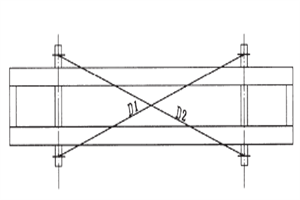 |
|D1-D2|≤5mm |
| 2 |
Height difference of trolley track joint and Joint gap d and e |
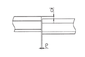 |
d≤lmm
e≤2mm |
| 3 |
Lateral dislocation of track joint f |
 |
f≤1mm |
| 4 |
Height difference of two rails at the same section perpendi cular to the direction of trolley traveling △h |
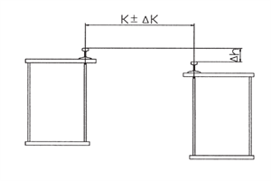 |
1.k≤2m △h≤3m
2.6.6m≥k>2m △h≤0.0015k
3.k>6.6m△h≤ 10mm
4. bias-rail girder△K= ±3mm
5. right-rail girder Middle span:△ K=+ 1 ~ +7mm End:K=±2mm |
| 5 |
Limit deviation of the span△S |
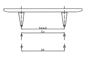 |
1.S≤26m △ S≤± 8mm and S1-S2≤± 8mm
2.S>26m 时 △ S≤±10mm and S1
S2≤±10mml. |
| 6 |
Leg verticality requirement |
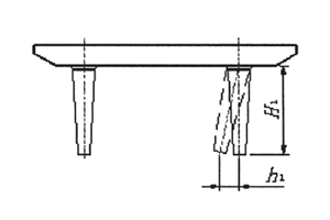 |
Verticality of rigi dity leg and main girder in the span direction h1≤H1/2000 |
| 7 |
Camber and upwarp degree of main girder |
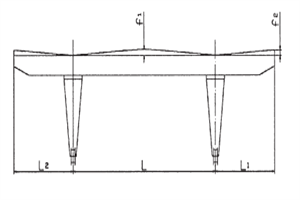 |
Fabrication of gantry and assembly shall ensure camber in middle f1 no less than 0.7S/1000 after
static load test,upwarp degree of effective cantilever end f2 no less than 350 |
| 8 |
Horizontal bending of main girder |
|
Middle-rail box girder and semi-bias-rail box girder shall be no more than S3/2000 (S3 is length of rib plate at both end, measured from rib plate which is 100mm away from upper flange plate) Maxi mum shall be no more than 20mm,f3<20. when Gn≤ 50t,convex to walkway side. |
2.3. Gantry crane trolley installation
Generally speaking, assembly of the trolley has been done and commissioned in workshop. After to the using units, it can be installed on gantry after necessary checks and adjustment.
According to the technical requirements of the drawing (see random diagram ), the trolley by separate transports for various reasons shall be reassembled and tightened. The trolley reassembled should check if the dimension of the trolley wheels conforms to the technical requirements.
2.4. Gantry crane traveling mechanism installation
The crane traveling mechanism has been assembled and has passed the commissioning by the manufacturer. After the assembly of crane traveling mechanism and lower cross beam, it should be checked according to the following requirements. It also applicable to the acceptance check after overhaul.
2.4.1 Check benchmark
The outside of wheels should be taken as benchmark when checking the span, lateral deviation and vertical deviation. (usually process a groove as mark).
2.4.2 check of wheels lateral deviation
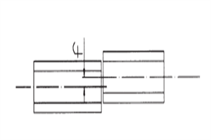
When installing wheels by boring, the tangent value of deflection angle Φ (see Figure 4 ) of the wheel axis should not exceed the regulations of Table 2.
When using angle bearing box, measure the end-face of wheels to control wheel deflection, the measured value | P1-P2 | (see Figure 4 ) for the four-wheeled crane and trolley should not more than the regulations of Table 3, but the deflection direction at the same axis should be contrary. Any combined form meets the requirements, as is shown in Figure 5.
For the Crane and trolley with more than 4 wheels, two wheels under single balance beam (balance bogie ) are shown in figure 3, the distance between all wheels does not exceed L/800 on the same track, and they do not control deflection direction of the wheels.
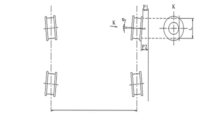
Figure 4 lateral deviation of the wheelsFigure 5 Combined form of the wheel lateral deviation
Table 2
| mechanism working duty |
M1 |
M2 ~ M4 |
M5 ~ M7 |
| tanФ |
four wheels |
0.0008 |
0.0006 |
0.0004 |
| over four wheels |
0.001 |
0.0009 |
0.0008 |
Table 3
| mechanism working duty |
M2~M5 |
M6~M7 |
| | P1 - P2 | |
L/1000 |
L/1200 |
2.4.3 Measurement of the span
The requirements see item 5 in table 1.
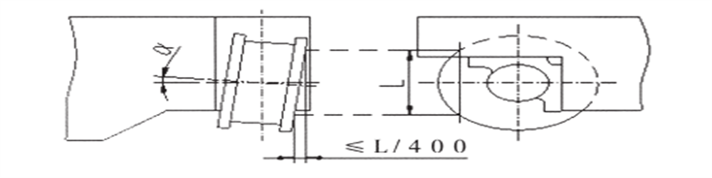
2.4.4 Measuring the vertical deflection of the wheel
When measuring the deflection of the wheel, the upper-plane of rail should be taken as the bench-mark. The deflection angle of the wheel axis should be controlled in the following scope, when directly installing the wheels shaft by boring.
-0. 0005≤tanα≤0. 0025
When using angle bearing box, measure the end-face of wheels to control vertical deflection, the measured value should not more than L/400 (L is measuring length ) , see Figure 6.
Figure 6 vertical deflection of the wheel
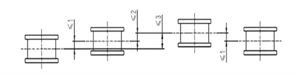
2.4.5 The idiostatic difference of wheel under the same lower cross beam
It should not exceed 2mm when having two wheels. It should not exceed 3mm when having 3 wheels or more. It should not exceed 1mm at the same balance beam.
Figure 7 the idiostatic difference of wheel
2.5 Gantry crane electrical equipment installation
- 2.5.1 All installation and wiring should be done according to the electrical principle drawing, wiring diagram and general layout.
- 2.5.2 Before installation, study carefully the above-mentioned drawings and technical conditions, get familiar with the reciprocity of elements and operational principles in order to quickly solve the problems which may occur during the installation and commissioning.
- 2.5.3 All the electrical equipment and elements should be cleared up and checked before installation. All of them should be flawless, running well, no lock and looseness. They must conform to the drawings such as types, specifications, close and open order of contact, etc. Some of them need to be adjusted according to the drawings.
- 2.5.4 Check the insulating properties of electrical elements such as motor, hydraulic brake, carbon brush, contactor, relay and resistance, etc. Measure their insulation resistance with Meg ohm meter. If any value is less than 0. 5 megohm, drying treatment must be done. It must be installed until passing the check.
- 2.5.5 Check the pressure between carbon brush of motor and slip ring, the pressure for all carbon brushes in one motor must be same. The carbon brush should contact with slip ring completely. When grinding the carbon brush, the edge of the brush should not be ground to round.
- 2.5.6 The hydraulic brake should be filled with hydraulic oil according to the instruction.
- 2.5.7 Check the pressure among controller, contactor and head of relay. Adjust it if each one is higher or lower than that regulated.
- 2.5.8 Operation pendent of controller shall be flexible and shift places should be clear.
- 2.5.9 Install all electrical equipment and parts according to the general drawing of electrical and other erection drawings.
- 2.5.10 The control cabinet, resistor and other heavier equipment on the walkway are supposed to be linked on the main frame tightly. And their positions are allowed to be adjusted according to the drawing.
- 2.5.11 The resistors should be close to the control panel as soon as possible and thus make the lead shortest. The resistors are allowed to be piled less than 5 boxes in order to avoid them being overheated. The resistors should be placed along the direction of parallel main beam to reduce shake and ventilate.
- 2.5.12 For the wires and cables of the resistors, the vertical part can be arranged on the right or left of the resistors but it should not affect assembling or disassembling of the resistors;and the horizontal part can be wound with asbestos rope or other high-temperature-proof materials.
- 2.5.13 The lead of resistors should be correctly connected according to the instruction. If it is found that motor contributes less power such as the joystick in the right place and the crane cannot lift the rating load, or the crane and trolley cannot move, check the connection of the resistors first. Usually it can be judged according to the specifications and quantity of the resistors. If necessary, it can be measured with electro-bridge (all the leads to the motor should be disassembled at this time. )
- 2.5.14 For the system driven by double motors, the resistance value of resistors for the two motors should be close and flexible resistance (including resistance of the lead) should be as close as possible (there is no flexible resistance in the method directly controlling rotor resistance with cam contacting points ). Check all the connections in the cabin. Eliminate looseness or falling connections if there is any and ensure all the connections are in good condition.
- 2.5.15 Before installing control cabinet, electrical elements and wires must be check carefully. There are not any damage for elements, especially the extinguisher cover of the contactor and the auxiliary contact etc. Check if the contactor and relay can run normally, accuracy and reliability of all kinds of interlock. Oil dirty (rustproof oil need to be painted before leaving factory ) on the contactor gag bit must be cleaned.
- 2.5.16 Check if relay operation at any time conforms to the setting value of factory technical documents requirements.
- 2.5.17 The gradient of control panel is not allowed larger than 5°in order to ensure the panel works in order. The passageway in front of the panel should be more than 500mm (600mm recommended) and the clearance at the back of the panel should not be less than 100mm for normal maintenance.
- 2.5.18 Before installing limit switches, carefully check if they are flexible and reliable. After installing, check if their wiring is right and adjust them in turn. After the protection mechanism arrives at limit position, check if feeler lever will open the limit switch. The distance between limit switches of crane and trolley and safety ruler should be suitable adjusted. The switch will be damaged when it is too tight, and they may lose protective function when it is too loose. For LX7 type switch (installed at the end of drum ) , the angle of contact must be adjusted (the range from 12°to 300°) to ensure power is off when hook rises to limit position. After adjusting the angle, cam should be compressed for fear of loosening in the course of running.
- 2.5.19 The insulator of crane conductor must be complete without any cracks, and fixed firmly on electric conducting frame. The conductor must be tightly pressed on conducting slide wire. Any spark during operation shows bad contact. The reason may be the loose contact between the conductor and the conducting slide wire or nastiness on the working surface, or both.
- 2.5.20 For the sake of safety, the cabin is usually installed on the opposite side of the crane conducting slide wire. If they must be installed on the same side, fence or net must be added for protection (the fence or net shall be provided and installed by the user ) .
- 2.5.21 When installing the trolley conducting device, first straighten the electric cables to eliminate the torsion, then put the cables orderly on end point clamp, the cable pulleys and festoon pulley according to the drawings. Drive the trolley to the limited position opposite to the driver's cab, then unlash cables, adjust the position of festoon pulley to keep the length of every section basically consistent and maintain certain relaxation, the sagging angle maintains about l20. After adjustment, fix cables firmly in the end point clamps and festoon pulleys with cable cleats. The drive the trolley to the limited position near the driver's cab again, adjust cables to keep the suspending length of every period basically consistent, fix cables firmly onto the pulleys with cable cleats. Bind the cables tightly with band every 500 ~ 700mm. In order to guarantee every cable tightly bound, rubber sheet should be under laid on the pulleys. Then install towing steel-rope, adjust its length to guarantee steel-ropes bear force during running, finally connect the two ends of cables to the junction boxes on the bridge and trolley separately.
- 2.5.22 The environmental temperature for the crane is -25~45℃and CFR type cable should be adopted. When environmental temperature is higher than 50℃, CEFR type cable should be adopted. When environmental temperature is lower than -25℃, YHD type cable should be adopted.
2.6 Gantry crane use of bolts
Some components of the crane need to be connected by bolt on site. You should note the following points:
- 2.6.1 The components joint surface should not have attachments such as rust, oxide skin, oil, paint etc, and should not have water stains and moisture. Before connecting, rustproof oil on the joint surface should be cleaned up.
- 2.6.2 Steel sheet and section steel of the joints should be straight. Before connecting, the burr of sheet edges and holes should be eliminated to ensure close connection.
- 2.6.3 When connecting, nut should screw to bolt freely. If bolt don't match with nut or screw gets damaged, they should be abandoned.
- 2.6.4 The common bolts allow to be corrected by beating central bar when the holes of steel fasteners are not concentric, rather than screwing bolts by compulsory beating for fear of damaging the screw to affect quality.
- 2.6.5 The reamed holes are forbiden to aim at holes by beating central bar. They must be reamed again if several holes dislocation and make new bolts to ensure quality.
- 2.6.6 When assembling bolts, the reamed bolts should be assembled first, then assemble the other bolts in turn.
- 2.6.7 When screwing the bolts, they should be tightened symmetrically rather than the order of bolts arrangement.
- 2.6.8 When installing, according to required construction torque to screw by torque wrench, only allow exerting torque on the nut.
- 2.6.9 Construction torque of high strength bolt is shown in table 4.
| bolt performance level |
bolt nominal diameter (mm) |
| M12 |
M16 |
M20 |
M22 |
M24 |
M27 |
M30 |
| 8.8S |
70 |
145 |
286 |
386 |
483 |
719 |
975 |
| 10.9S |
85 |
208 |
403 |
543 |
702 |
1017 |
1384 |