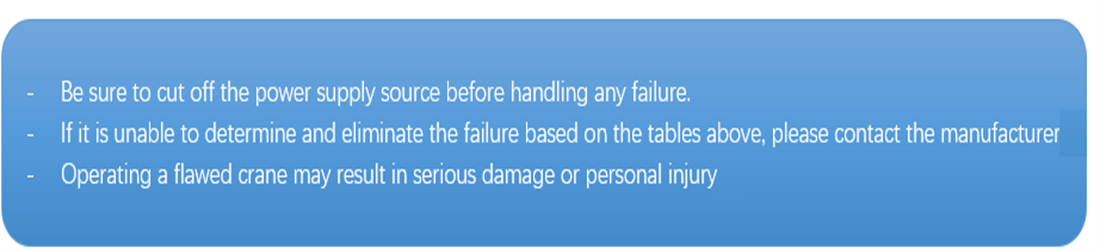
| Precautions |
| - - In case of sudden power failure during the work,before the work is recovered, it’s required to place all controller handles to “zero position” and only in this way can master contactor be started. - -When moving direction of the crane and trolley is changed, it is required to place the handle in “zero position”and the operation in reverse direction can be carried out only after the mechanism stops operation completely. -- lt is forbidden to realize parking by operating the crane or trolley in a reverse direction. -- When pushing the handle, it will realize acceleration or deceleration gradually. Before the crane moves, operation personnel shall consider the distance of start and stop. |
| No. | Items | Methods, Contents, and Requirement | Recommended Treatments | Cycle | |||||
| Day | Week | Month | Quarter | Year | |||||
| 1 | Technical Documents |
Attached documents | Check that the attached drawings, the operation manual and the certificate are complete. | Correct and improve | ○ | ||||
| 2 | Inspection records | Check that the past inspection records are complete and there are no untreated defects. | Correct and improve | ○ | |||||
| 3 | Maintenance records | Check that the past maintenance records are complete and there is no non-validated maintenance | Correct and improve | ○ | |||||
| 4 | Other documents | Check that the past maintenance records are complete and there is no non-validated maintenance. | Correct and improve | ○ | |||||
| 5 | whole crane | Operating environment | Visually check that the operating environment has no factors influencing operation safety. | Treat according to the enterprise management system and the operation specifications | ○ | ○ | ○ | ○ | ○ |
| 6 | Appearance | Visually check that the crane has no trash, sundries, left tools in it. | Clean | ○ | ○ | ○ | ○ | ○ | |
| 7 | Visually check that the crane has no trapped oil and water in it. | Clean | ○ | ○ | ○ | ○ | |||
| 8 | Visually check that there are no defects on its surface like serious corrosion, paint peeling. damage, etc. | Prevent corrosion/ repair | ○ | ○ | |||||
| 9 | Wheel loading | Visually check that every wheel has no suspension. | Adjust/repair | ○ | ○ | ○ | |||
| 10 | Span | The span deviation should meet the requirements of relevant crane standards. | Adjust/repair | ○ | |||||
| 11 | Metal structure | Main beam, end beam, trolley frame, balance beam, track roller frame, etc. |
Visually check the crane for the corrosion, cracks and plastic deformation of metal structures like the main beam, end beam, trolley frame, track roller frame, balance beam, etc. and they should meet the requirements set forth in Section 3.9 ofGB6067.1-2010. | Prevent/corrosion/repair/change | ○ | ○ | |||
| 12 | Visually check that the welds of main stressed structures have no visible cracks | Repair | ○ | ○ | |||||
| 13 | Fastenings | Stressed structure safety device fastenings |
Visually check that there are no damage and looseness in the hinge shafts and bolts of main stressed structures and safe by devices. | Change/adjust | ○ | ○ | |||
| 14 | Fastenings of mechanisms and electrical components | Visually check thar there are no damage and looseness in the connecting bolts of the motor, speed reducer gearbox, brake, coupling, electric cabinet, and other components | Change/festen | ○ | ○ | ○ | |||
| 15 | Mechanism | Hoisting mechanism |
Check that the hoisting mechanism has no abnormal noise and vibration by a no-load test. | Maintain | ○ | ○ | ○ | ○ | |
| 16 | Long travelling mechanism | Check that the operating mechanism has no abnormal noise and vibration by a no-load test. | Maintain | ○ | ○ | ○ | ○ | ||
| 17 | Visually check that there is no deflection, track biting, etc. influencing the cranes operation. | Adjust/change | ○ | ○ | ○ | ||||
| 18 | Trolley travelling mechanism | Check that the trolley operating mechanism has no abnormal noise and vibration by a no-load test. | Maintain | ○ | ○ | ○ | ○ | ||
| 19 | Visually check that there is no deflection, track biting, etc. influencing the trolleys operation. | Adjust/replace | ○ | ○ | ○ | ||||
| 20 | Slewing mechanism |
Check that the slewing mechanism has no abnormal noise and vibration by a no-load test. | Maintain | ○ | ○ | ○ | ○ | ||
| 21 | Telescoping mechanism |
Check that the slewing mechanism has no abnormal noise and vibration by a no-load test. | Maintain | ○ | ○ | ○ | ○ | ||
| 22 | Crane power supply unit |
Check that the crane power supply unit has no abnormal noise and vibration by a no-load test. | Maintain | ○ | ○ | ○ | |||
| 23 | Trolley power supply unit | Check that the crane power supply unit has no abnormal noise and vibration by a no-load test | Maintain | ○ | ○ | ○ | |||
| 24 | Lifting spreader mechanism | Check that the trolley power supply unit has no abnormal noise and vibration by a no-load test. | Maintain | ○ | ○ | ○ | |||
| 25 | Lubricating system |
Visually check that the lubricating system should work normally with no clogging and leakage. | Maintain | ○ | ○ | ○ | |||
| 26 | Electric hoist | Check that the block has no abnormal noise and vibration by a no-load test. | Maintain | ○ | ○ | ○ | |||
| 27 | key component | Lifting spreader | Check that the lifting appliance welds and structures have no wear-out and deformation and abnormal noise influencing safety | Repair/change | ○ | ○ | ○ | ||
| 28 | Visually check that the lifting appliance pins do not get loose or pull out, and the pin-end retainers safe and effective. | Fasten/repair/change | ○ | ○ | ○ | ||||
| 29 | Visually check that the hook locking device and the hook nut locking device are effective. | Adjust/repair/change | ○ | ○ | ○ | ||||
| 30 | Check the surface crack, deformation, abrasion and corrosion of the forged hook according to the method specified in GB/T10051.2 and GB/T10051.3, and relevant items shall comply with corresponding requirements. | Repair/change | ○ | ○ | |||||
| 31 | Check the suspension fork structure, lifting beam structure and weld joint by visual inspection, and there shall not be any crack or plastic deformation | Repair/change | ○ | ○ | ○ | ○ | |||
| 32 | Check the surface of laminated plate hook according to the method specified in GB/T10051.13 and GB/T 10051.14, and there shall not be any crack or serious deformation. In addition, the rivet shall not be loose, the clearance of hook pieces shall be normal, and the lining at the mouth of hook shall not have any obvious abrasion, crack or plastic deformation. | Fasten/adjust/repair/change | ○ | ○ | |||||
| 33 | Pulley | Visually check that the trolley should meet the requirements set forth in Section 4.2.5 ofGB6067.1-2010. | Repair/change | ○ | ○ | ||||
| 34 | Visually check that the pulley can turn flexibly. | Lubricate/adjust | ○ | ○ | |||||
| 35 | Visually check that the pulley stopper is safe and effective. | Repair/change | ○ | ○ | |||||
| 36 | Reel/Drum | Visually check that the reel should meet the regulations set forth in Section 4.2.4.5 inGB6067.1-2010 | Change | ○ | ○ | ○ | |||
| 37 | Steel wire rope | Check the steel rope according to the methods specified in GB/T5972 and make sure it meet the requirements. | Change | ○ | ○ | ○ | |||
| 38 | Visually check that the steel rope should have no obvious mechanical damage. | Repair/change | ○ | ○ | ○ | ○ | |||
| 39 | Visually check that the steel ropes of the reel and the pulleys have no disengagement from the | Fasten/adjust | ○ | ○ | ○ | ○ | ○ | ||
| 40 | groove. | Fasten/adjust | ○ | ○ | ○ | ||||
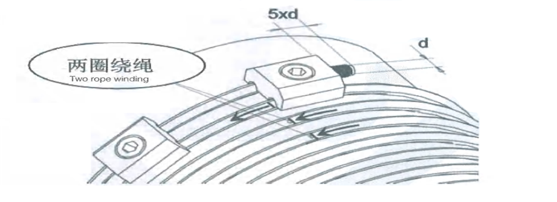
| 41 | Brake | Visually check that the fixation at the end of the steel rope can meet requirements; be sure the press plate is in good operation condition; the end length of the steel rope should be greater than 5 times the diameter. | Lubricate/adjust | ○ | ○ | ○ | ○ | ||
| 42 | Visually check that the lubrication of turning points and slewing points meet requirements. | Maintain | ○ | ○ | ○ | ○ | ○ | ||
| 43 | Check through a no-load test that the hoisting mechanism can work properly | Change | ○ | ○ | ○ | ||||
| 44 | Wheel | Visually check that the brake should meet the requirements set forth in Section 4.2.6.7 of GB6067.1-2010. | Fasten/adjust/repair/change | ○ | ○ | ||||
| 45 | Coupling | Visually check that the wear and deformation of wheel flanges and treads meet the specifications set forth in Section 4.2.7 fGB6067.1-2010 | Fasten/repair | ○ | ○ | ○ | ○ | ||
| 46 | Reducer | Visually check that the coupling has no defects looseness, oil leakage, and abnormal vibration and noise in operation. | Fasten/repair | ○ | ○ | ○ | |||
| 47 | check that the running reducer has no abnormal noise, vibration, oil leakage and overheat | oil | ○ | ○ | ○ | ||||
| 48 | Bearing | Visually check that the oil level should be within the required range. | Change | ○ | ○ | ||||
| 49 | Trolley rail | Visually check that the bearing has no abnormal noise and temperature rise. | Adjust | ○ | |||||
| 50 | joint gap and height difference to make sure they meet relevant standards. | Change | ○ | ○ | ○ | ||||
| 51 | Visually check that the track has no cracks and serious wear-out. | Fasten/change | ○ | ○ | ○ | ||||
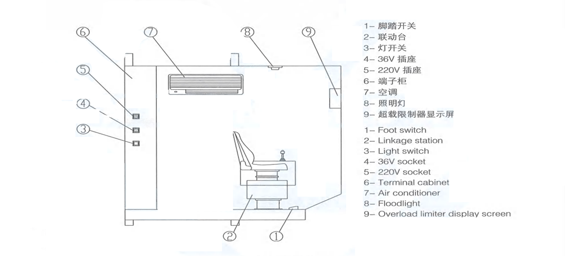
| 52 | Cab | Visually check that the track press plates have no damage and looseness. | Fasten/repair | ○ | ○ | ○ | |||
| 53 | Visually check that the cab connecting parts have no sealing-off, looseness and cracks. | Repair/change | ○ | ○ | ○ | ○ | |||
| 54 | Visually check that the cab has no electrified parts inside and the indoor floor is well insulated. | Clean/change | ○ | ○ | ○ | ○ | |||
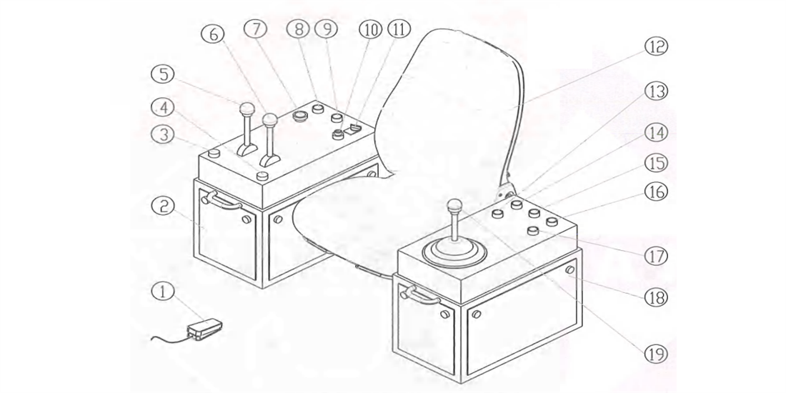
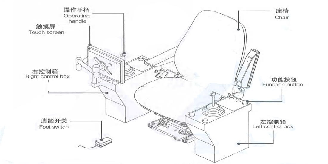
| 55 | Electrical control system | Power supply | Visually check that the door, windows, glass and lock of the cab are not damaged and they should be clean and present a clear sight | Maintain | ○ | ○ | ○ | ○ | ○ |
| 56 | Control device | Visually check that the power supply works properly. | Repair/change | ○ | ○ | ○ | ○ | ||
| 57 | Visually check that all buttons are flexible and effective and the lower insulation protection of the control lever is not damaged. | Adjust/change | ○ | ○ | ○ | ○ | ○ | ||
| 58 | Visually check that the control levers of all mechanisms are flexible and free of jamming and the gears can feel clearly and the zero lock is effective. | Repair/change | ○ | ○ | ○ | ○ | |||
| 59 | Power feeding device | check that the shells of remote control device and have no damage and the control buttons are marked clearly and correctly and functions normally. | Adjust/repair/change | ○ | ○ | ||||
| 60 | Motor | Visually check that the live indicating devices are complete and effective; the soft cable protective coating has no serious aging, damage, bulging; the cable reeling device are complete and effective; and the current collector is contacted reliably. | Repair | ○ | ○ | ||||
| 61 | Measurement of motor insulation resistance should meet the requirements of various product standards | Adjust/change | ○ | ○ | |||||
| 62 | Main power switch | Visually check that the motor slip-ring has no burns and carbon brush wear, and the pressure should be proper. | Adjust/change | ○ | ○ | ○ | |||
| 63 | Control cabinet/console and electric facilities | Visually check that the main power supply switch functions properly. | Adjust/change | ○ | ○ | ○ | |||
| 64 | Visually check that the door switch of the control cabinet is flexible and the lock is secure. | Change | ○ | ○ | ○ | ||||
| 65 | Visually check that the electrical wires and components in the control cabinet have no overheat, scorch, and melting; and the components have no damage in the surfaces and the shell does not shed. | Adjust/change | ○ | ○ | ○ | ||||
| 66 | Visually check that electrical connection and earthing are reliable and cables have no serious cracking and damage. | Clean/fasten | ○ | ||||||
| 67 | Visually check that the mark of every section of lines is clear and the connection is not loose. | Repair/change | ○ | ||||||
| 68 | Check through a function test that the lines have no overheat, the insulation and earthing resistance are satisfactory | Adjust/change | ○ | ○ | |||||
| 69 | Communication | Check through a function test that the wiring terminals, contactors and relays are in good contact; visually check that the arc-control device is complete. | Maintain | ○ | ○ | ○ | ○ | ○ | |
| 70 | Lighting | Check through a function test that the communication between the host computer and the central control room is good. | Repair/change | ○ | ○ | ○ | ○ | ○ | |
| 71 | Air conditioning system | check that the lighting equipment has no damage. | Maintain | ○ | ○ | ○ | ○ | ||
| 72 | Hydraulic system | Visually check that the air conditioners in the electrical room and the cab work normally. | Fasten/repair | ○ | ○ | ○ | ○ | ○ | |
| 73 | check that the hydraulic system has no oil leakage. | Maintain | ○ | ○ | ○ | ||||
| 74 | Pneumatic system | Visually check that the hydraulic system works normally and has no abnormal noise and overheat. | Fasten/repair | ○ | ○ | ○ | ○ | ○ | |
| 75 | check that the pneumatic system has no oil leakage | Maintain | ○ | ||||||
| 76 | Safety protection device | Lifting height limiter | Visually check that the pneumatic system works normally and has no abnormal noise. | Fasten/repair | ○ | ○ | ○ | ○ | ○ |
| 77 | Secondary lifting height limiter | Check through function testing that the lifting height limiter is fixed securely and functions effectively. | Fasten/repair | ○ | ○ | ○ | |||
| 78 | Travel limiter | Check through function testing that the secondary lifting height limiter is fixed securely and functions effectively. | Fasten/repair | ○ | ○ | ○ | ○ | ○ | |
| 79 | Slewing limiter | Check through function testing that the travel limiter is fixed securely and functions effectively | Fasten/repair | ○ | ○ | ○ | |||
| 80 | Slewing locking device | Check through function testing that the slewing limiter is fixed securely and functions effectively | Fasten/repair | ○ | ○ | ||||
| 81 | anti-crash device | Visually check that the slewing locking device has no deformation, damage and looseness | Fasten/repair | ○ | ○ | ○ | |||
| 82 | Buffer and end stopper | Visually check that the anti-crash device has no deformation and damage and functions effectively | Fasten/repair/change | ○ | ○ | ||||
| 83 | Load lifting limiter | Visually check that the buffer has no deformation and damage and the end stopper has no deformation and open welds. | Fasten/repair | ○ | |||||
| 84 | Overspeed protection device | Check through function testing that the load lifting limiter is fixed securely and functions effectively. | Change | ○ | |||||
| 85 | Interlock protection | Visually check that the overspeed protection device is not absent. | Adjust/change | ○ | ○ | ○ | ○ | ||
| 86 | Visually check that the interlock device has no damage and short-circuit. | Repair/change | ○ | ○ | ○ | ||||
| 87 | Earthing protection | Check through function testing that the electrical interlock device is normal and reliable. | Repair/change | ○ | ○ | ○ | |||
| 88 | Electrical protection | Visually check that the earthing device is intact and functionally effective. | Change | ○ | |||||
| 89 | Safety monitoring and management system |
Visually check that the electrical protection has no damage, including short-circuit, voltage loss, zero and overcurrent. | Adjust/repair | ○ | ○ | ○ | ○ | ○ | |
| 90 | Emergency stop switch | Visually check that the control units of the safety monitoring and management system work normally. | Repair/change | ○ | ○ | ||||
| 91 | Sound and light alarming | Once activating the emergency stop switch, the crane should stop immediate; the emergency stop switch should not reset automatically; after being manually reset, it should enable the crane to recover normal operation when restarted. | Repair/change | ○ | ○ | ○ | |||
| 92 | Marks and warning signs |
Check through function testing that the sound and light alarm can work properly. | Repair/change | ○ | ○ | ○ | ○ | ○ | |
| 93 | Stair, step platform, walkway, railing | Visually check that the nameplate, tonnage mark and safety warning sign are clear and has no damage. | Fasten/repair | ○ | |||||
| 94 | Protective cover | Visually check that the stair, step, land form walkway, and railing are intake and secure. | Fasten/repair | ○ | |||||
| 95 | Maintenance cage |
Visually check that the protective covers of the rotating parts are secure, complete and intact. | Fasten/repair | ○ | |||||
| 96 | Conductive trolley line protective device | Visually check that the maintenance cage has no damage, the connection is not loose, and the protection is effective. | Fasten/repair | ○ | |||||
| 97 | Rail sweeper | Visually check that the conductive trolley line protective device is complete and intact. | Adjust/change | ○ | ○ | ||||
| 98 | Radiant heat protection device | Visually check that the clearance between the track sweeper and the track is 5mm~10m | Fasten/repair | ○ | ○ | ||||
| 99 | Fire-fighting equipment | Visually check that the radiant heat protection device is intact and connected firmly. | Adjust/change | ○ | ○ | ○ | ○ | ○ | |
| Precautions |
| --Only the casting crane (ladle crane) manufacturer’ s steel rope can be used. |
| --Unwinding the steel rope should prevent knotting or twisting. |
| --Cutting off the steel rope should take measures against strand spreading. |
| Table 8-2 Quantity of Steel Rope Clamps | |||||
| Nominal diameter of steel rope/mm | ≤19 | 19~32 | 32~38 | 38~44 | 44~60 |
| Minimum quantity/set of steel rope clamps | 3 | 4 | 5 | 6 | 7 |
.png)

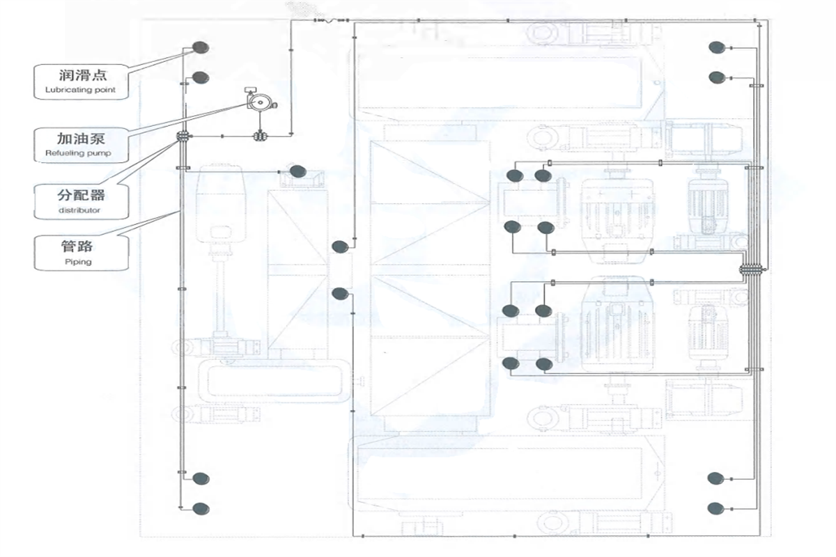
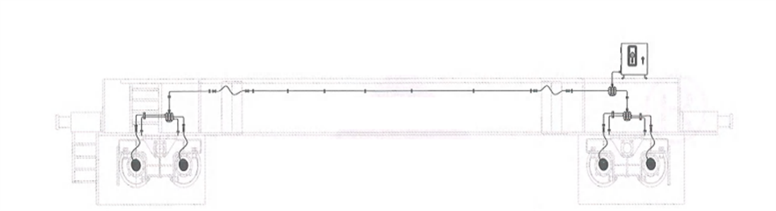
| Table 8-3 Crane Component Lubrication List | |||
| Lubricating component | Oil (grease) injection cycle | Oil (grease) injection measure | Recommended oil (grease) |
| Steel rope of main hoisting mechanism | Weekly | Heat the lubricating grease to 80-100C and coat to saturation | Special lubricating grease for exclusive use of steel rope |
| Steel rope of auxiliary hoisting mechanism | Every half month | Coating | Special lubricating grease for exclusive use of steel rope |
| Reducer | Initial using period change the oil within300 hours since the operation, then every 6months later | Injection oil quantity shall comply with the scale pointed by oil needle | L-CKD320 industrial heavy load gear oil |
| Electro hydraulic brake | Quarterly | Oil injection quantity shall comply with the height of oil hole | DB-25 hydraulic oil |
| Gear coupling | Monthly | Press-in by oil gun till overflow | No.2 common lithium-based grease |
| Universal coupling | Monthly | Press-in by oil gun till overflow | No.3 composite calcium-based grease |
| Reel coupling | Monthly | Inject oil into each oil hole successively. Where the oil hole is in lower part, press the oil in the hole by oil gun till overflow from spherical surface | No.3 extreme pressure lithium-based grease |
| Reel ring gear | Monthly | Coating until it is full | No.2 common lithium-based grease |
| Bearing | Weekly | Press-in by oil gun (oil injection pump) till overflow | common lithium-based grease |
| Motor | Yearly | Coating until it is full | No.2 common lithium-based grease |
| Hinged shaft | Monthly | Press-in by oil gun till overflow | No.3 composite calcium-based grease |
| Hinged point of brake, limit switch, etc. | Every 3 months | Coating until it is fill | No.2 common lithium-based grease |
| Table 8-4 Table of Reducer Fuel Charge | ||
| A1960 | 115L | L-CKC320 industrial heavy load gear oil |
| A1650 | 95L | |
| A1570 | 80L | |
| ZQ1000 | 60L | |
| ZQ850 | 40L | L-CKC220 industrial medium load gear oil |
| ZQ650 | 19L | |
| ZQ500 | 12L | |
| ZQ400 | 5L | |
| ZSC600 | 5L | |
| ZSC400 | 3L | |
| Note: be sure the reducer inner case keeps absolute clean before changing lubricating oil | ||
| Table 8-5 Bolt Torque Table | ||
| Specification | Tightening Torque | |
| Strength magnitude 8.8(Nm) | Strength magnitude 10.9(Nm) | |
| M4 | 2.7 | 4 |
| M5 | 5.4 | 7.9 |
| M6 | 9.3 | 14 |
| M8 | 23 | 33 |
| M10 | 45 | 66 |
| M12 | 77 | 115 |
| M14 | 125 | 180 |
| M16 | 190 | 280 |
| M18 | 275 | 390 |
| M20 | 385 | 550 |
| M22 | 530 | 750 |
| M24 | 660 | 950 |
| M30 | 1350 | 1900 |
| Table 9-1 Mechanical Failure | |||
| Failure | Causes and Consequences | Treatments | |
| Reducer | shell heating | Bearing failure; lack of lubricating oil in gears and bearings. (It is normal when the temperatuC7:C28re is not more than 40℃ above the medium temperature and the absolute value is not more than 80℃) | Check the lubrication and bearings; Change oil and bearings |
| Oil seeping of clipping plane and bearing cap | Loose connection, and sealant damage | Tighten, clean, and apply sealant | |
| Vibration | Loose connection, misaligned axle center of connecting pieces | Readjust, tighten, and reinforce the pedestal | |
| Vertical reducer runout | Deformation of connecting hinge shafts, and key damage | change the shaft, adjust and reinforce the hinge support, and change the key | |
| Gear pair | Tooth fracture | Overload or fatigue failure, tooth root cracks | Change |
| Gear pitting | Peeling off | Change it when the surface is more than 30% of the working surface, and the pit depth is more than 10% of the tooth thickness. | |
| Tooth wear | Starting or braking runouts | Change when the wear limit of the hoisting mechanism is 10% of the original tooth thickness and of the operating mechanism 15~25%. | |
| Gear | Improper lubrication | Change | |
| Spoke and rim cracks | Gear damage results in gearing chain damage | Change the hoisting mechanism, and repair the operating mechanism. | |
| Noise and clash | Improper machining and assembly: in adequate contact surfaces, tooth scars, tooth tip-root biting, skew assembly | Ensure accuracy, and no-load running-in | |
| Coupling | Cracks in coupling half | Coupling damage | change |
| Wear of connecting bolt holes | Impacts and vibration, bolt shear-off and load falling of hoisting mechanism at braking | change | |
| Tooth wear or fracture | Lack of lubrication, overload, overturn, coupling damage | Grease regularly; change when the tooth wear reaches 15% of the original thickness for the hoisting mechanism and 30% for the operating mechanism. | |
| Key groove wear or deformation | Key slippage leads to failure to transmit torque. | Change the hoisting mechanism, and repair the wear by welding for the operating mechanism | |
| pulley | No rotation of pulleys | Bearing damage | change |
| Uneven wear of pully groove | Uneven material, unacceptable installation and poor contact of rope and pulley | change | |
| pulley spindle wear reaches 3-5%ofits nominal diameter | Spindle damage | change | |
| Pulley tipping and loosening | On-shaft locating element loosening | fasten | |
| Pulley cracks or rim fracture | Pulley damage | change | |
| Rolling bearing | High temperature | Lack of lubricating oil and dirt; cracks | Remove dirt and grease or change |
| Tooth fling and clash | Damage of holders and rolling elements | Change bearing | |
| Brake | Failure to stop the falling of load and weight | A. Lever hinge is jammed; B. There is greasy dirt on the brake wheel or friction disc; C. The brake wheel or friction disc is serious worn; D. The main spring gets loose or damaged; E. The locknut and tie rod get loose; F. Engine impeller fails to turn agilely; G. The clearance of the brake shoe is too large. |
A. Remove the jamming and apply lubricant; B. Clean off the dirt; C. Change the friction disc; D. Change the main spring or locknut; E. Tighten up the locknut; F. Repair the engine; G. Adjust the clearance |
| Failure to open | A. The fiction disc sticks to the brake wheel; B. The moving hinge is jammed; C. The main spring has too large force; D. The brake push rod is bent; E. Inappropriate oil is used; F. The impeller is jammed; |
A. Cleaning; B. Remove the jamming and apply lubricant; C. Adjust the main spring force: D. Change the push rod; E. Change the oil according to the ambient temperature; F. Adjust the push-rod mechanism and check the electrical devices |
|
| Heating and friction disc coking | A. After releasing the brake, it fails to separate from the brake wheel unevenly, causing friction. B. The clearance between the brake shoes and the brake wheel is uneven or too small; C. The working surface of the brake wheel is rough. |
A. Adjust the clearance; B Adjust the clearance; C. Machine the brake wheel surface as required |
|
| Brake leaving its setting position; unsteady braking torque | A. The adjusting nut and the back nut are not tightened up; B. Threads are damaged. | A. Tighten up the nuts B. Change |
|
| Wheel | Noise or vibration | The rim is terribly worn. | change |
| Track biting in one direction | The lateral deviation of the wheel is excessive and the direction of deflection at both ends is not reverse. | readjust | |
| Different track biting back and forth | The operating motor or the brake is asynchronous. | Inspect and adjust | |
| Track biting in a section | The rail is installed incorrectly | Inspect and adjust the section of track | |
| Outer edge biting or inner edge | The span is wrong | Inspect and adjust | |
| Trolley track biting | The main beam sinks to bend inwards. | Repair the main beam | |
| Unsteady and inclined traveling | Rim wear is excessive; and the track is not level. | Change the wheel and adjust the track | |
| Wheel slip | There is grease dirt on the track. | Remove the dirt | |
| Table 9-2 Structural Failure and Treatments | |||
| Failure | Causes and Consequences | Treatments | |
| Main beam, end beam | Weld cracks | Centralized stress, overload and enlarging cracks involving rupture risks. | Disperse the stress, and repair the welds to stop them enlarging; overload prohibited |
| Main beam | Camber disappeared | Overload; trolley climbing | Flame straightening, stiffness and strength reinforcing and increasing |
| Oversized sidewise bending | Inadequate horizontal stiffness | Flame straightening | |
| End beam | Oversized sidewise bending | Inadequate horizontal stiffness and joint strength | Restored by professional technicians |
| Rail | Deformation | Loose connection, oversized tracks, and noise | Readjust and fasten bolts |
| Balance beam | Weld crack and deformation | Too large lateral force, track biting | Adjust and repair |
| Plate hook | Rivet loosening | Increased plate clearance; difficult for hanging hook | Rivet again |
| Trolley frame | Partial deformation | Weak structure excessively stressed; parts damaged | Rivet again |
| Table 9-3 Common Motor Failure and Treatments | |||
| Failure | Causes and Consequences | Treatments | |
| Even overheat of motor | A. The actual type of work exceeds the rating; B. The supply voltage is too low; C. The specified values are exceeded in the operating environment. |
A. Reduce the motor’s working frequency; B. Reduce the motor load at low voltage; C. Reduce the ambient temperature |
|
| Partial overheat of stator iron | Partial short-circuit of the silicon steel sheet of the iron | Remove the burrs and other faults causing short circuit and apply insulating paint | |
| Rotor overheat; great current surge of stator; failure to reach the full speed under the rated load | A. Poor contact between or open weld of coil ends neutral points or shunt winding; B. Poor connection between windings and slip rings; C. Poor contact in brush assembly; D. Interruption or short circuit of rotor circuit |
A. Inspect all the welds and remove external defects; B. Inspect windings and slip rings; C. Inspect and treat the brush assembly; D. Inspect and treat the rotor contactor or control the contact point |
|
| High vibration in working hours | A. Misalignment of motor shaft and reducer shaft; B. Bearing wear Rotor deformation | A. Measure and align the shaft concentricity; B. Inspect and change the bearing; C. Inspect and machine the rotor | |
| High noise in working hours | A. Phase loss of stator; B. Mal-compression of stator iron; C. Rolling bear wear; D. Slot wedge expansion; E. Low stator voltage F. Stator voltage imbalance; G. Phase loss of rotor; H. Rotor voltage imbalance |
A. Inspect and remove motor phase loss; B. Press or change; C. Inspect or change; D. Saw off the expanded part or change; E. Find out the cause of low voltage; F. Eliminate the imbalance; G. Inspect and eliminate rotor phase loss; H. Eliminate imbalance |
|
| Overtemperature | Motor oversize, ventilating passage blockage, coil earthing, stator and rotor scuffing, bearing wear | Stop use it and eliminate the failure | |
| Table 9-4 Common Failure and Treatments of Electrohydraulic Thruster | |||
| Failure | Causes and Consequences | Treatments | |
| Failure to actuate | A. Power failure B. Mechanical hinge points are inflexible C. No oil in the oil cylinder D. The brake spring force is too large. |
A. Inspect the power circuit B. Remove the failure at hinge points and add lubricant C. Add oil according to the specified oil level D. Adjust or change the thruster |
|
| Inadequate travel | A. Oil shortage in the cylinder B. The mechanical part is jammed | A. Add oil according to the specified oil level B. Eliminate the failure of the mechanical part |
|
| Slow and weak movement | A. Oil shortage in the cylinder B. High oil viscosity C. Air exists in the oil cylinder D. Too large braking force E. Low motor voltage |
A. Add oil according to the specified oil level B. Change suitable oil as required C. Eliminate the air in the oil cylinder D. Adjust the spring force E. Inspect the power supply line |
|
| Motor overheat | A. Thruster overload B. Low motor voltage |
A. Adjust the braking force B. Inspect the power supply line |
|
| Table 9-5 Common Failure and Treatments of Circuits and Components | |||
| Failure | Causes and Consequences | Treatments | |
| Crane failing to actuate | A. No power supply B. Button failure of the portable controller |
A. Inspect the power supply source and emergency button B. Inspect the button and wiring |
|
| Only one-way action of hoisting and operation |
A. Wiring failure B. Limiter actuated |
A. Inspect the wiring B. Leave the limiting position |
|
| Main air switch trip | Short-circuit or earthing failure of the main circuit | Inspect the main circuit | |
| Control circuit air switch tripping | Earthing failure of the control circuit | Inspect the circuit | |
| Overcurrent relay actuating at operating the controller | A. Lower ratings B. Mechanical part jammed C. Brake not opened D. Excessive load |
A. Adjust the operating value to 2.25 times of the rated motor current B. Inspect the mechanical part C. Inspect and adjust the brake D. Inspect whether the load is too large |
|
| Limit switch fails to function | A. Contact welded B. Earthing or short-circuit failure in circuits C. Sneak circuits in the circuit D. Inaccurate adjusting point |
A. Repair the switch contact B. Inspect the circuit C. Inspect the circuit D. Readjust the cam position |
|
| Relay contact fails to release after power failure | A. Contact welded B. Earthing or short-circuit failure in circuits C. Sneak circuits in the circuit D. Actual wiring and drawing inconsistence |
A. Repair the contact B. Inspect the circuit C. Inspect the circuit D. Correct the wiring according the circuit diagram |
|
| The controller is out of order | A. Disconnection or wrong wiring in circuits B. Poor contact of the contact C. Malfunction of the locating mechanism D. Cam disc loosening E. Wrong contact action |
A. Inspect the circuit B. Repair the contact C. Restore the locating mechanism D. Adjust and fasten the cam disc E. Repair the contact |
|
| The controller contact is burnt. | A. Poor contact B. Controller overload C. Arc control device damaged D. Controller closing procedure errors E. Line errors |
A. Repair the contact B. Change the load or the controller C. Change the arc control device D. Inspect and correct E. Inspect the line |
|
| The temperature of the relay and contract coils is too high. | A Higher coil voltage B. Larger coil suction. C. Clearance existing between moving or fixed irons in suction |
A. Adjust the coil voltage to the rating B. Adjust the contact spring pressure C. Remove the clearance |
|
| The pull-in noise of the relay and contact is too loud. | A. Larger coil suction B. Oil dirt on the bonding surface of moving or fixed irons C. Misaligned magnetic circuit D. Moving part jammed |
A. Adjust the contact spring pressure B. Remove oil dirt C. Adjust the magnetic circuit to align it D. Eliminate the additional resistance |
|
| The pull-in action of the relay and contact is slow. | A. Longer distance between moving or fixed irons B. Larger friction of movable parts C. Lower coil voltage |
A. Adjust the initial position of the moving and fixed irons B. Add lubricant to reduce friction C. Adjust coil voltage |
|
| The relay and contact release slowly. | A. Inadequate contact pressure B. Magnetic remanence or oil dirt on the iron C. Moving part jammed |
A. Adjust the contact spring B. Eliminate magnetic remanence or oil dirt C. Eliminate additional resistance |
|
| The contact of the relay and contactor is burnt because of overheating. | A. Inadequate contact pressure B. Oil dirt on the contact C. Inadequate contact capacity |
A. Adjust the contact spring B. Remove |
|