1. Installation and Commissioning of Double Girder Overhead Crane
.png)
The installation and maintenance of the crane should be carried out by specialized organization with relevant qualifications!
1.1 Equipment storage
After the double girder overhead crane is transported to the site, the installation work should be completed within 6 months and the equipment should enter normal maintenance work. Due to user’s reasons, if the user places the equipment for a long time, they should make a storage and maintenance plan for the equipment. When the equipment is transported to the site, it should be, counted and maintained by the user every 2 months (including rust removal and painting for damaged surfaces, rust prevention of high-strength bolt joint surfaces, bearing boxes ‘s grease filling and dust prevention, and waterproofing and moisture-proof treatment of electrical and hydraulic components). A complete record of the damage and maintenance status should be kept for easy reference. Storage should be strictly carried out in accordance with the storage conditions specified on the cargo box. If not indicated, the following should be strictly followed: Maintain a complete damage and maintenance record for easy reference. Storage should be strictly carried out in accordance with the storage conditions specified on the cargo box. If not indicated, the following should be strictly followed:
- 1) The steel structure binding parts should be placed on a flat site with high terrain and no accumulated water, The equipment body should be cushioned off the ground with wood, and for ultra-high and easily falling objects, they should be reinforced firmly. Warning signs should be used around to indicate the danger of falling and keep away. The joint surface of the bearing rotation and high-strength bolts should be inspected for damage to the waterproof and rust prevention treatment. After damage, it should be repaired in a timely manner to prevent water ingress, dust ingress, and rust.
- 2) The packaging box should be placed in a covered area without falling rain or standing water to prevent rainwater from entering the box interior and damaging internal components.
- 3) The packaging boxes of electrical and hydraulic components should be placed in a dry indoor room to prevent electrical components from getting damp, etc. For boxes with strict requirements for moisture, regularly check the condition of the desiccant and replace it immediately if it expires.
1.2 Open package inspection
1.2.1 Check the model, specifications, and quantity of double girder overhead crane accessories according to the packing list to see if they meet the requirements of the technical documents, and if there are complete random documents;
1.2.2 Check the crane for deformation, damage, and rust.
1.2.3 Check that the steel wire rope must not have any damage, bending, twisting, or looseness that affects its performance and safety;
1.2.4 Use a multimeter to check if the electrical box (cabinet) wiring is correct and prevent loose wire ends during transportation;
1.2.5 Remove oil stains or rust preventive oil from the wheel tread.
1.3 Installation
1.3.1 Installation method
Mobile crane is used to install. Please refer to the "Installation Construction Plan" for specific steps.
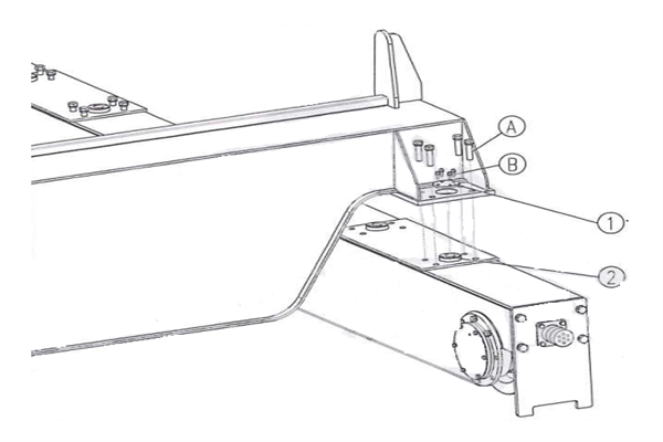
1.3.2 Assembly of main girder and end girder
1) Place the driving end beam on the rail and temporarily fix both ends;
2) Remove the end cover 1;
3) Lift the main beam, gently move it above the end beam, and locate it according to the positioning ring;
4) Tighten the bolts according to the recommended torque in 7.6;
5) Cover the end cap;
6) After assembly, measure the limit deviation of the double girder overhead crane span △S: when S≤10m, △S=±2mm; when S>10m, △S=±[2+0.1 (S-10)] mm;
7)Ensure that the diagonal difference measured from the reference point of the wheel is not greater than 5mm.
Figure 1-1 main end beam assembly
1.End cap 2. Locating ring A, B. Fastening bolt
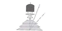
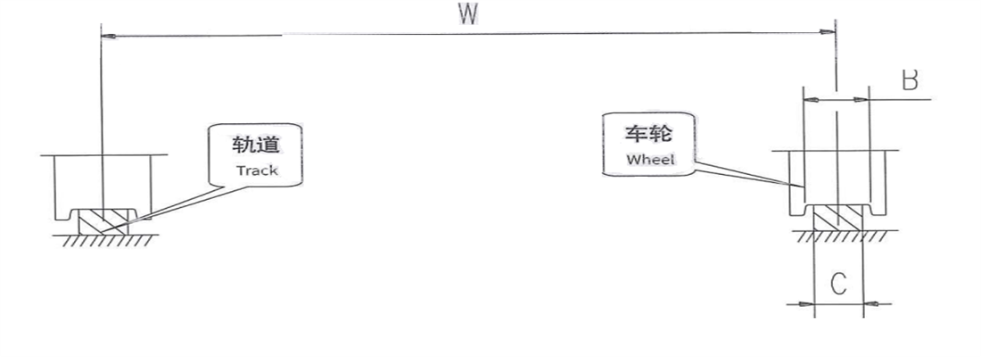
1.3.3 Hoisting trolley installation
Figure 1-2 trolley installation
1) Check the width of the trolley wheel groove (B) and the width of the track tread (C). Standard condition is B=C+15mm
2) Check and ensure that the rail Centre-to-Centre distance (W) on the main beam is consistent with trolley’s rail gauge.
3) Lift the trolley onto main beam rail and check the vertical and horizontal deviation of the wheels.
4) Check and ensure that the fixing hole of the traction arm is on the same side as the trolley’s feeding line.
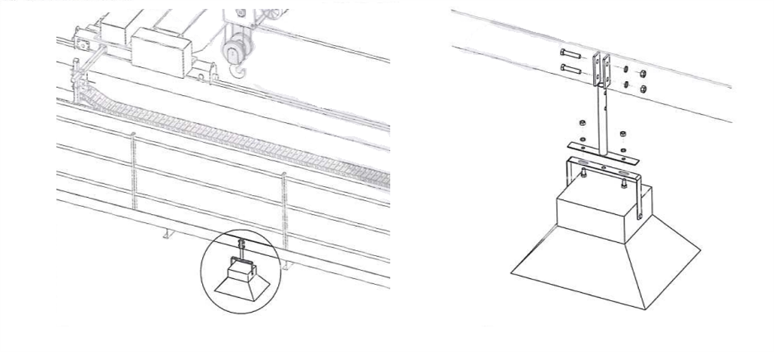
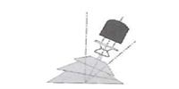
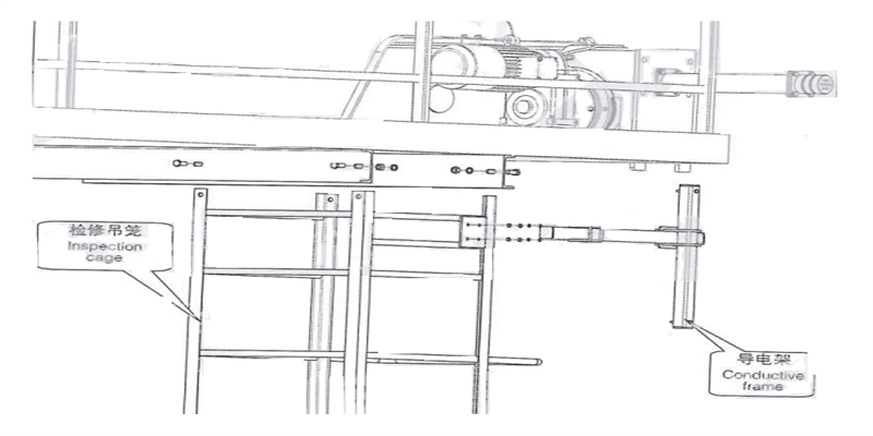
1.3.4 installation of maintenance cage and pantograph
The maintenance cage is installed under the transmission side walkway, near the power supply sliding wire side, and is equipped with a crane conductive frame device. When the power supply sliding wire malfunctions, maintenance personnel can enter the suspension cage through the inspection hole on the walking platform for maintenance work.
Figure 1-3 installation of maintenance cage
1) Insert the maintenance cage between the two channel steels under the walking platform and fix it with bolts;
2) Fix the conductive frame to the connecting plate of the maintenance cage with U-bolts as shown in the diagram;
3) After adjusting the position of the conductive frame, tighten the bolts according to the recommended torque in 7.6.
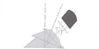
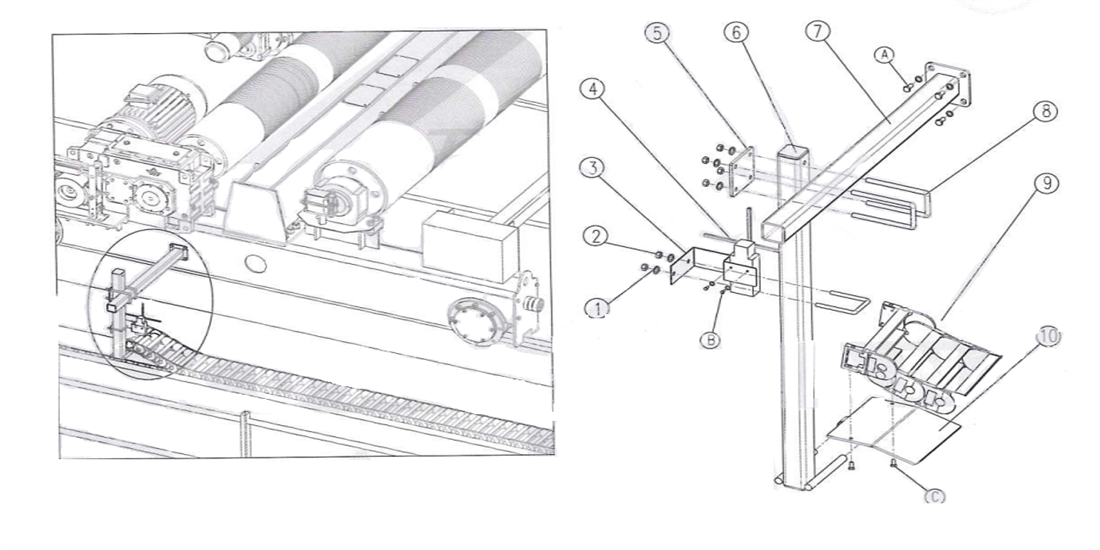
1.3.5 Installation of trolley conductive frame
1) Fix the traction arm D with bolts on the outer side of the trolley end beam as shown in the diagram;
2) Install rectangular tube 6 on the traction arm with U-bolts 8 and pre tighten it to secure:
3) Install limit switch 4 on bracket 3, and then use U-bolts to install it on the rectangular tube, pre tighten and fix it:
4) The drag chain support plate 10 is set on the two round steel bars at the bottom of the rectangular tube 6, and the plane should be facing upwards;
5) Fix the energy chain 9 on the support plate with bolts;
Figure 1-4 installation of trolley pantograph
1. Gasket 2. Nut 3. Holder 4. Limit switch 5. Junction plate 6. Rectangular tube 7. Draft arm
8.U-type bolt 9. Energy chain 10. Drag chain mounting plate A, B, C. Fastening bolt
6) After adjusting the position, tighten each U-bolt according to the recommended torque in 7.6
Figure 1-5 schematic diagram of energy chain spacing
| Matters needing attention |
| -- Before installation, check and ensure that the energy chain guide groove is horizontal, the interface is smooth and tight, and the guide groove is not deformed; |
| -- Ensure that the moving head of the drag chain is always at the center of the guide groove; |
| -- The height between the upper and lower energy chains H ≈ 135mm; |
| -- If necessary, the excess length of the traction arm can be removed; |
1.3.6 Installation of trolley travelling limiter
1) The trigger device holder is fixed at the edge of the cover plate on the main beam, trigger rod is placed in the groove, and the bolt is pre tightened for fixation
2) Adjust the position of the trigger rod and cross type limit switch, and tighten each fastening bolt according to the recommended torque in 7.6
Figure 1-6 Installation of trolley travelling limiter
| Position |
Name |
Quantity |
Position |
Name |
Quantity |
| A(Trigger gear) |
Deck |
2 |
Limit switch device |
Cross-type limit switch |
1 |
| Trigger role |
2 |
Foundation |
1 |
| Fastening bolt |
4 |
Fastening bolt |
2 |
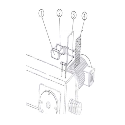
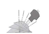
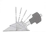
1.3.7 Installation of long travelling limit
1) Long travelling limit adopts photoelectric switches, which are installed at both ends of the end beam on the sliding wire side of the double girder overhead crane;
2) The height of reflector plate ③ is adjustable;
3) After adjusting the position, stick the reflective paper on reflective plate, and when single crane is running, stick it on the object opposite the parking space.
Figure 1-7 Long travelling limit installation
1- Photoelectric switch 2- Switch support 3- Reflector 4- Reflective paper
1.3.8 Installation of cable pendant
According to different control methods, the cable pendant has different installation positions.
Cab control +ground control or ground control +remote control, the control line of cable pendant is fixed at the electric control box on the walking platform;
During ground operation, cable pendant relies on a cable pulley and moves freely along the C-shaped steel track suspended on the passive side of the main beam
1) Insert the crossbar ④ into the fixed seat ② in the direction of the arrow in sequence, and pre tighten the bolts;
2) After adjusting the position, use a lifting clip ③ to combine the crossbar ④ and C
shaped steel ⑤together;
3) Tighten the bolts according to the recommended torque in 7.6;
4) If there are joints in C-shaped steel, ensure that the joints are smooth
5) Install the cable pulley into the C-shaped steel track in sequence;
6) Insert the pendant wire plug into the traction pulley socket, fix the steel wires on both sides of the plug according to the diagram, and finally form a circle at the end of the handle wire for easy adjustment.
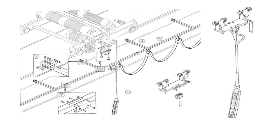
Figure 4-8 cable pendant installation
1. C-type steel junction 2. Fixed plug 3. Suspension clamp 4. Overarm 5. C-type steel 6. Manual switch box and cable pulley
1.3.9 Installation of bridge lamp
The bridge lamp is installed under the transmission side walkway for work lighting, and the number of arrangements depends on different spans
Figure 1-9 installation of bridge lamp
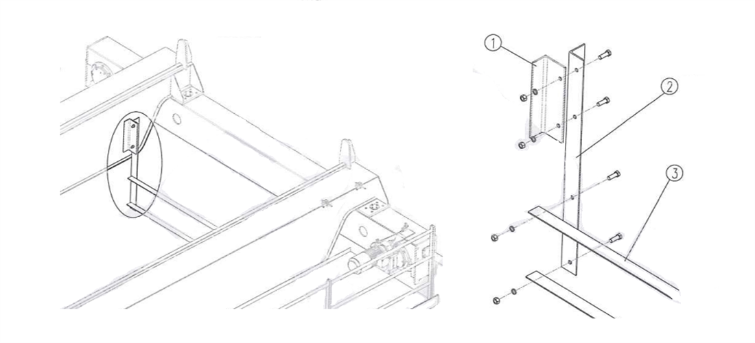
1.3.10 Installation of the hook preventing bracket
The hook preventing bracket is installed at the end of the main beam near the sliding wire to prevent the hook or steel wire rope from touching the sliding wire.
Figure 1-10 Installation of hook preventing bracket
1. Angle iron support 2. Angle iron vertical bar 3. Angie iron cross bar
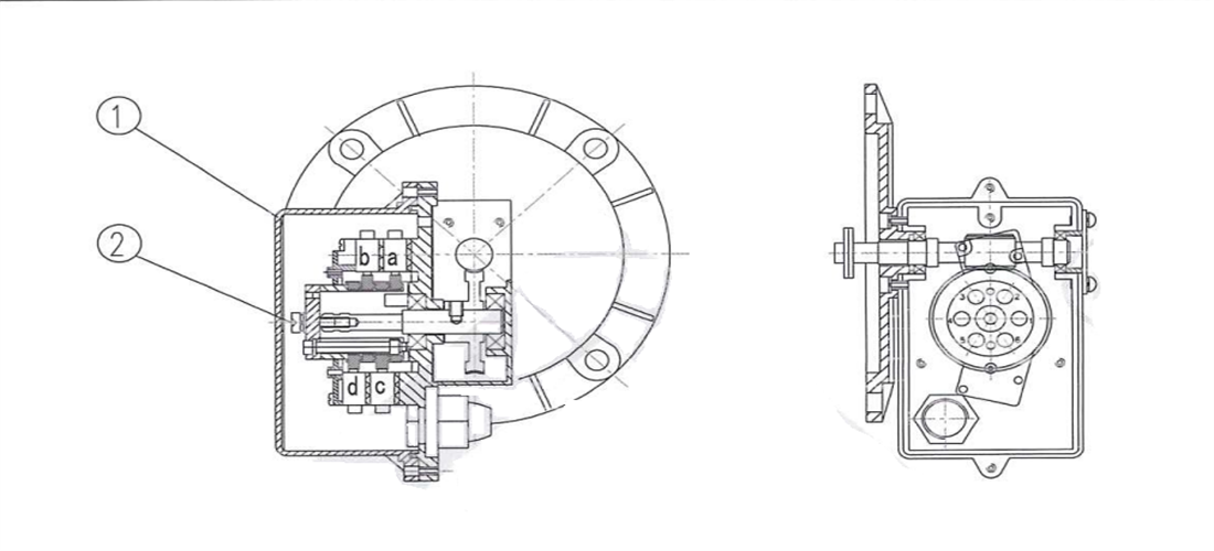
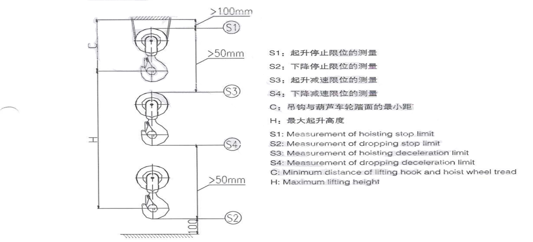
1.4 Commissioning of lifting limit switch
The lifting limit switch is installed at the end of the drum and drives the worm gear to rotate through the drum shaft. When the four sets of cams on the worm gear shaft also rotate to a certain position, the flange part of the cam contacts the limit switch, causing the limit switch to act, cutting off the upward or downward power source, and stopping the lifting appliance at the limit position. Equipped with four sets of limit switches, which can provide two protections for both ascending and descending, namely deceleration limit and stop limit.
Figure 1-11 lifting limit switch
a: Hoisting deceleration limit b: Hoisting stop limit c: Dropping deceleration limit d: Dropping stop limit
1: Operculum 2: Lock screw of regulating mechanism
2) Loosen the locking screw ②;
3) Turn the screw "d" until the limit switch "d" is just activated
4) Tighten the locking screw and test the operation. The descent action must stop at the set distance;
5) Repeat steps 1-4 until the correct setting is reached;
6) Lower the hook to a distance of approximately 150mm from the ground;
7) Loosen the locking screw ②;
8) Turn the screw "c" until the limit switch "c" is just activated;
9) Tighten the locking screw and test the operation. The speed of the descent action must be reduced to low speed at the set distance;
11) Lift the hook until the top of the hook pulley is approximately 150mm away from the bottom of the trolley frame;
12) Loosen the locking screw ②;
13) Turn screw "a" until the limit switch "a" is just activated:
14) Tighten the locking screw and test the operation. The speed of the lifting action must be reduced to low speed at the set distance
15) Repeat steps 11-14 until the correct setting is reached;
16) Lift the hook until the top of the hook pulley is approximately 100mm from the bottom of the trolley frame;
17) Loosen the locking screw ②;
18) Turn screw "b" until the limit switch "b" is just activated
19) Tighten the locking screw and test the operation. The lifting action must stop at the set distance;
20) Repeat steps 16-19 until the correct setting is reached;
21) Tighten the locking screws and close the housing cover.
2. Test Run of Double Girder Overhead Crane
Before using the double girder overhead crane, the inspections and commissioning listed below must be carried out at least. In some cases, a more thorough inspection is required. The scope of inspection depends on the operating range and usage.
2.1 No-loading inspection
2.1.1 Check the connection of electrical equipment
1) Check and ensure that the connections and wiring diagrams of the electrical devices are consistent. Special attention should be paid to checking connections that affect the safety and control of the double girder overhead crane.
2) Check the wiring method. Ensure that the wires do not cause obstacles due to staggered wiring structures during double girder overhead crane operation.
2.1.2 Inspection of cable pendant
1) Check and ensure that the manual switch and suspended control wire are in good condition.
2) Check and ensure that the manual switch is at the correct height.
3) Press the direction button on the manual switch and check to ensure that the direction
indicated on the button is consistent with the direction of action.
4) Check the operation of the emergency stop button.
If it is not necessary, do not press the emergency stop button arbitrarily.
2.1.3 Checking work noise
Determine whether there are installation errors based on the noise emitted during lifting and travelling.
-- If the lifting motor makes loud intermittent noise, the problem may be on the power supply. Check and correct the phase sequence of the power supply.
-- If the operation produces loud noise accompanied by severe vibration, it is possible that the wheels are causing "rail gnawing" phenomenon. Check the fit between the wheels and the track.
Do not use double girder overhead crane until the cause of undesired noise or vibration has been identified and eliminated
2.1.4 Inspection to lifting limit switch
Check the operation of the limit switch by running the hook to the upper and lower limit positions.
For safety reasons, the lifting limit switch must be adjusted before each test run
2.1.5 Inspection to travelling limit switches
Adjust the triggering position of the limit switch. Check the operation of the limit switch by running the double girder overhead crane to the triggered position.
For safety reasons, the triggering position of the travelling limit switch must be adjusted before each test run
2.1.6 Travelling inspection for hook pulley
Check and ensure that the pulley can rotate freely.
2.1.7 Inspection of wire rope
1) Check and ensure that the wire rope is not damaged.
2) Check and ensure that the wire rope is wrapped around the drum and pulley in the correct way.
3) Check the fixation of wire rope’s end part.
-The starting load of the wire rope should be about 10% of the rated load. The load should be lifted to the total lifting height by 5-10 times
2.1.8 Inspection for brake operation
Check and ensure that the lifting brake can operate normally in both the upward and downward directions.
2.2 Inspection to rated lifting capacity
2.2.1 Inspection for motor current
Check the motor current of each phase during the lifting operation under rated load. The current of all phases should be balanced and cannot exceed motor’s rated current.
2.2.2 Inspection for travelling mechanism
1) Check that the acceleration and braking actions of travelling mechanism can operate smoothly.
2) Run at least 3-5 times over the entire length of the main beam. Remove loose paint from rail.
2.3 Inspection to overloading condition
Check the operation of overload protection device under overloaded (110-125% of the rated load). When the load exceeds triggering load of the overload protection device, the overload protection must be able to effectively prevent lifting action.
2.4 After inspection
2.4.1 Cleaning
Check and ensure that all tools and additional materials used during installation have been removed from crane and rails.
2.4.2 User training
Ensure that double girder overhead crane operators and supervisors understand the necessity of user training.
2.4.3 Delivery documents
1) Check the randomly delivered documents. Ensure the accuracy of the file content, and ensure that the reference data in the file is consistent with the data on the nameplate.
2) Write a test run record of the crane and keep it with other crane’s documents.
3. Usage and Operation of Double Girder Overhead Crane
3.1 double girder overhead crane work level
The safety and effective operation of a double girder overhead crane depends on the correct classification of the crane's working level. According to FEM standards, double girder overhead crane working level is determined by the following parameters:
-- Load spectrum
-- Average daily working hours
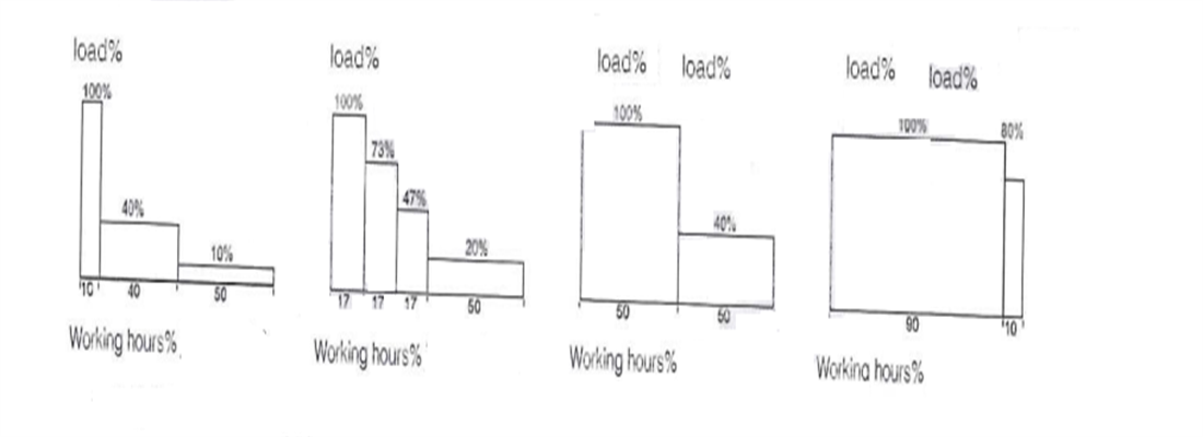
3.1.1 Load spectrum
The load spectrum is determined by the following table:
| Light |
Medium |
Heavy |
Super heavy |
| Occasionally full load |
Occasionally full load |
Repetitive full load |
Almost always full load |
| Usually light load |
Usually light load |
Usually common load |
Extremely heavy load |
| Small fixed load |
Common fixed load |
Heavy fixed load |
|
3.1.2 Average daily working hours
The average daily working time of a double girder overhead crane can be calculated from crane travelling time (hours/day)
t=2*H*N*TV*60
H=average lifting height (m)
N=number of working cycles per hour
T=Daily working hours (h)
V=Lifting speed (meters/minute)
3.1.3 determine double girder overhead crane’s working level
| Load spectrum |
Average daily working hours(hrs/day) ISO/FEM |
| ≤0.5 |
≤1 |
≤2 |
≤4 |
≤8 |
≤16 |
| Light |
|
|
M3/1Bm |
M4/1Am |
M5/2m |
M6/3m |
| Medium |
|
M3/1Bm |
M4/1Am |
M5/2m |
M6/3m |
M7/4m |
| Heavy |
M3/1Bm |
M4/1Am |
M5/2m |
M6/3m |
M7/4m |
|
| Super heavy |
M4/1Am |
M5/2m |
M6/3m |
M7/4m |
|
|
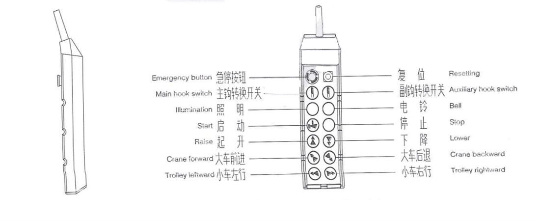
3.2 Cable pendant operation
The lifting and travelling of the double girder overhead crane are controlled by a button type pendant, connected by an aviation plug, and the symbols and markings comply with FEM standards. The pendant is suspended under double girder overhead crane’s control box through cables, and is equipped with start, stop, action buttons, changeover and emergency switch and other devices. Both lifting and lowering use dual speed buttons, and the operation should transition from slow speed (first level) to fast speed (second level); When descending, the object should be lowered to a suitable height at high speed and then lowered to the designated position at low speed.
The appearance and wiring of the cable pendant are different due to different control methods.
Figure 3-1 Cable pendant
Use the following steps to start the double girder overhead crane in standby mode:
♦ Rotate the [emergency stop button] clockwise to release;
♦ Press the [Start] button to enter the working state of double girder overhead crane;
If the cable pendant contains a transfer switch, it must be ensured that the transfer switch is in the appropriate position before use.
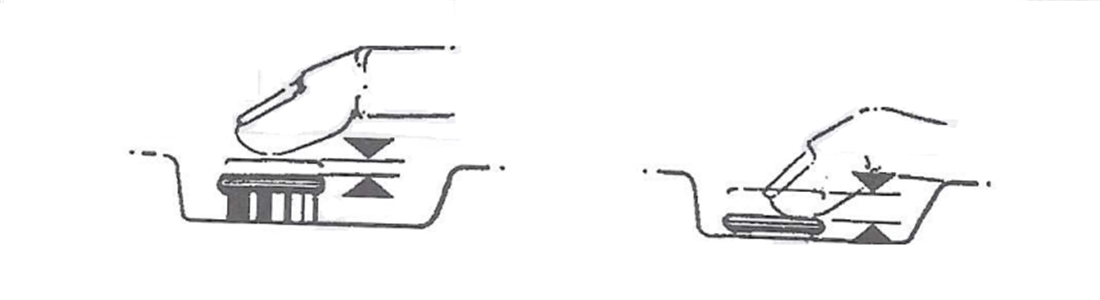
♦ Release button→stop
♦ Press first level→slow speed
♦ Press all→fast
Figure 3-2 Two speed button control
After operating the double girder overhead crane, return it to the standby state as follows:
♦ Move the crane to the correct stop position and stop all crane movements;
♦ After all double girder overhead crane movements have stopped, press the [Emergency Stop Button] and the button will be locked
| Matters needing attention |
| ♦ When lifting each time, the button should be jogged at low speed to tighten the wire rope, and then the load should be lifted at low speed; |
| ♦ When the load is lifted from the ground level, it should be ensured that the load is balanced. |
| ♦ When the load avoids all obstacles, it can switch to high speed to continue. |
| ♦ When lowering the load, the speed should be controlled by lowering from high speed to low speed. |
3.3 Operation in driver’s cabin
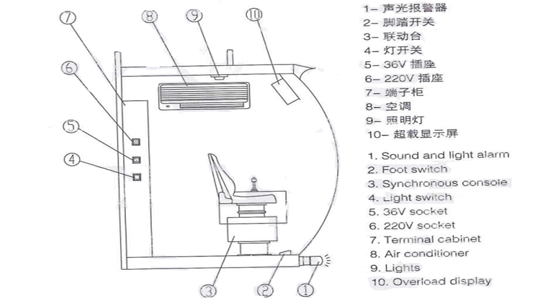
3.3.1 Driver's cab layout
The driver's cab is a closed structure with three circular windows, all tempered glass, and equipped with adjustable height seats. It is equipped with an operating console, foot operated sound and light alarm, air conditioning, overload limiter display screen, lighting, and 36V, 220V switch sockets and other facilities.
Figure 3-3 Cab
3.3.2 Electric hoist type double girder overhead crane operation platform
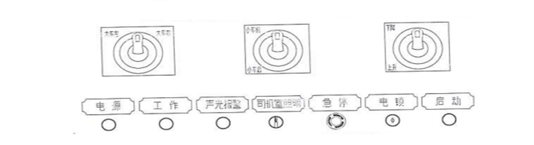
3.3.2.1 Layout
The front handles of the operation console separately control the lifting and lowering of the hook, as well as the travelling of the bridge and trolley. The rear seats are equipped with various functional buttons and indicator lights.
Figure 3-4 layout of operation platform
3.3.2.2 Function description
► Left handle: controls the left and right movement of the cart, divided into two gears in sequence;
► Middle handle: controls the front and rear movement of the car, divided into two gears in sequence;
► Right handle: controls the lifting hook to rise and fall;
► Power indicator light: After the external power supply is powered on, this indicator light will turn on the work indicator light; After pressing the [Start] button, this indicator light will light up;
► Sound and light alarm: Press this button, the sound and light alarm will flash and accompanied by an audible alarm;
► Driver's cab lighting: Control the lighting inside the driver's cab;
► Emergency stop: Red mushroom shaped button device. Equipped with a rotating unlocking mechanism. Pressing this button can quickly cut off the power supply of the main circuit of double girder ► overhead crane in an emergency, protecting the safety of equipment and personnel.
► Electric lock: can only be activated by inserting the key
► Start: Press this button to send control power and connect the contactors of each mechanism
| Handle position |
Function description |
 |
Zero position:
The mechanism is not operating. If it is already running, it will slow down to a stop. |
 |
Slow First Gear:
When the handle is pushed from a vertical position to this position, the mechanism will accelerate to the set slow speed;
When the handle is pushed from second gear to this position, the mechanism will slow down to the set slow speed. |
 |
Fast second gear:
The mechanism accelerates to the set speed |
3.3.2.3 Combination Control Console for open winch double girder overhead crane
The QTA-C series combination control console and seat are installed in an integrated manner, equipped with a master controller, zero position self-reset and locking devices, which can control the motor start, brake, speed regulation, and direction change of the double girder overhead crane. The panel is equipped with indicator lights and various function buttons.
The combination control console is mainly used in control circuits with AC 50Hz (60Hz), rated voltage 380V (440V), rated current AC2, 6A, DCO, 3A and below to control the motor start, speed regulation, braking, commutation, and other functions of the double girder overhead crane. Double mechanism linkage/single action can be achieved according to different operating conditions. Integrated installation, button operated handle, in line with ergonomic concepts, equipped with WLK type master controller with clear hand feel, clear gear position, zero position self-reset and locking device. PLC module and human-machine interface touch screen can also be installed according to different needs.
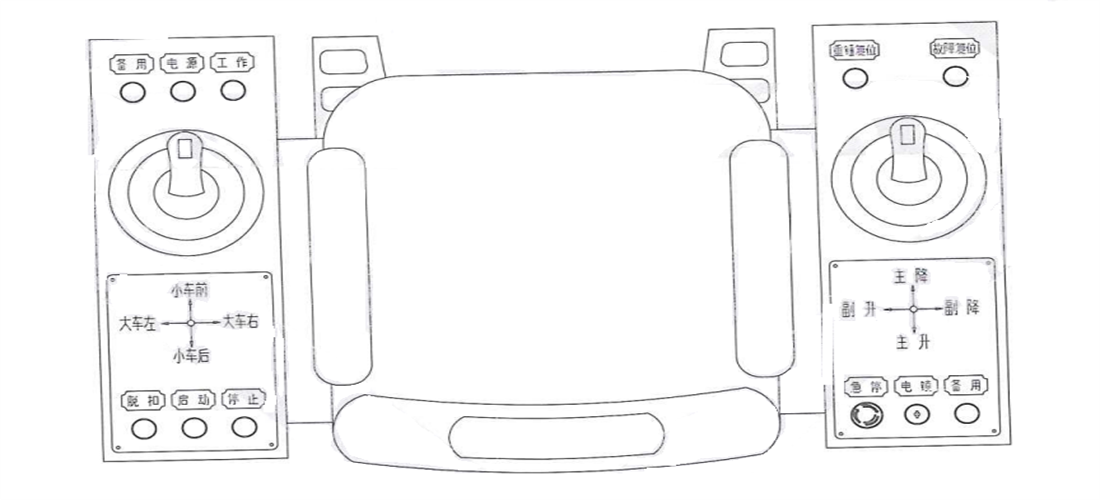
Figure 3-5 Layout of open winch type combination control console
3.3.2.4 Function description
When using, insert the electric lock key and turn the key switch clockwise. Press the "Start" button to turn on the green power distribution indicator light. After completing the start process, press the "Stop" button to turn off the green power distribution indicator light. Turn the key switch counterclockwise to the initial position and remove the electric lock key. When the driver leaves the linkage platform, they must stop the operation, return the handle to the zero position, and remove the electric lock key.
The descriptions of each handle and function button are as follows:
♦ Main and auxiliary hook operating handle: controls the lifting and lowering of the main and auxiliary hooks;
♦ Large and small car operating handles: control the left and right movements of the bridge and trolley, which are divided into four gears in sequence;
♦ Power indicator light: After the external power supply is powered on, this indicator light will light up;
♦ Start indicator light: After pressing the [Start] button, this indicator light will light up;
♦ Electric lock: can only be activated by inserting the key;
♦ Start: Press this button to send control power and connect the contactors of each mechanism;
♦ Stop: Press this button to cut off the control power and disconnect the contactors of each mechanism;
♦ Tripping: After pressing this button, cut off the main power supply;
♦ Backup: for expanding other functions;
♦ Gravity hammer reset: After the main circuit is powered off, press and hold this button to power on the main circuit and operate the hook to lower. After the hammer is reset, release the button;
♦ Fault reset: After troubleshooting, press this button to restore to normal state;
♦ Emergency stop button: red mushroom shaped button device. Equipped with a rotating unlocking mechanism. Pressing this button can quickly cut off the power supply of the main circuit of the double girder overhead crane in emergency situations, protecting the safety of equipment and personnel;
♦ Light switch: controls the bridge lighting.
3.3.4 Lifting mechanism operation
1) Press the operating handle to pull it back from the zero position, and the weight will rise. The lifting speed will increase in order from one to four gears. After the handle is pulled back to the zero position, the lifting will stop.
2) Press the operating handle to push forward from the zero position, the weight will descend, and the descent speed will increase in sequence from one to four gears. After the handle is pulled back to the zero position, the descent will stop.
3) When the lifted object is overloaded, the overload limiter will sound an alarm and signal to limit the lifting, and the lifting mechanism can only operate in a downward direction.
4) The lifting mechanism is equipped with lifting and lowering limit limits. After stopping the limit action, it will prohibit the operation of the lifting mechanism in that direction, but it can be operated in the opposite direction.
3.3.5 Bridge travelling and trolley travelling operation
- 1) Press the operating handle to push forward from the zero position, and the trolley mechanism will move forward. The walking speed will increase in order from one to four gears. After the handle is pulled back to the zero position, the forward movement will stop.
- 2) Press the operating handle to pull back from the zero position, the trolley mechanism will move backward, and the walking speed will increase in order from one to four gears. After the handle is pulled back to the zero position, the backward movement will stop.
- 3) Press the operating handle to push it from zero to the left, and the double girder overhead crane mechanism will move left. The walking speed will increase in order from first to fourth gears. After the handle is pulled back to zero, the crane will stop.
- 4) Press the operating handle to push it from zero to the right, and the crane mechanism will move to the right. The walking speed will increase in order from one to four gears. After the handle is pulled back to zero, the crane will stop.
- 5) The travel mechanism of the large and small vehicles is equipped with forward and backward terminal limits. After stopping the limit action, the movement of the travel mechanism in that direction will be prohibited, but it can be operated in the opposite direction.
| Hnadle position |
 |
 |
 |
 |
 |
| Function |
Zero position: The mechanism does not operate |
Slow first gear: The mechanism accelerates to the setting speed |
Slow second gear: The mechanism accelerates to the setting speed. |
Fast third gear: The mechanism accelerates to the setting speed. |
Fast fourth gear: The mechanism accelerates to the setting maximum speed. |
| Matters needing attention |
| ♦ When there is a sudden power outage during work, all controller handles should be placed in the "zero position" before resuming work, in order to start the main contractor and make the motors of each mechanism work; |
| ♦ When changing the direction of movement of a large or small vehicle, the handle must be set to the "zero position" and the mechanism must be completely stopped before it can be operated in the opposite direction; |
| ♦ Do not use reverse braking to stop; |
| ♦ When the handle is pushed, the double girder overhead crane will gradually accelerate or decelerate. Before moving the double girder overhead crane, the operator should consider the distance between start and stop. |
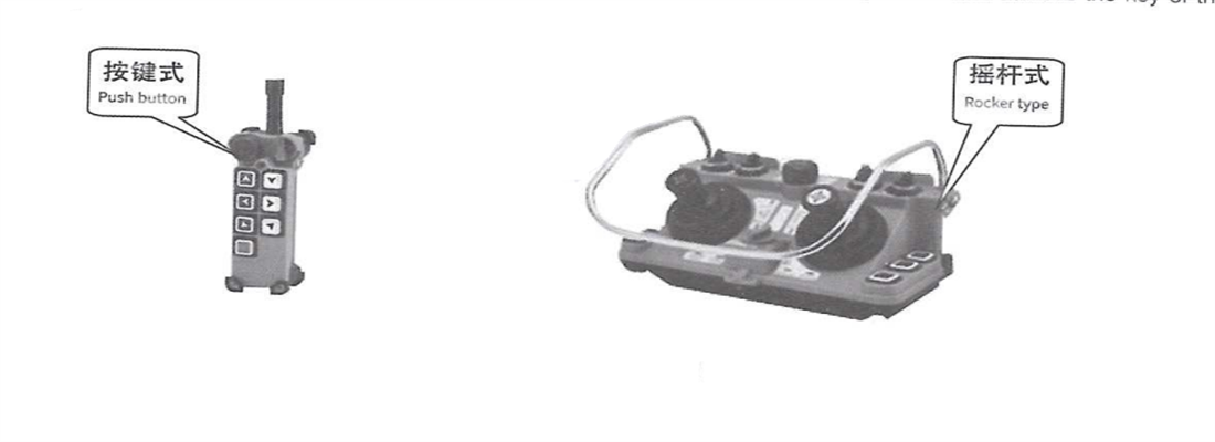
3.4 Remote controller operation
The wireless remote control operation is equipped with a remote transmitter and a remote receiver, which are installed in the control cabinet. With wireless remote control, the operator only needs to carry a lightweight transmitter, freely move around, and choose the best safe visual position for operation.
According to the different functions used, the remote control is divided into single (dual) speed button type and joystick type, and the operation manual will be provided randomly.
When using, first insert the remote control key into the remote control, press the green start button to activate the remote control receiver, rotate the "transfer switch" on the linkage platform or flashlight door to the "on" position, and then proceed with remote control operation.
When it is necessary to switch back to the linkage platform or the flashlight door for operation, rotate the "transfer switch" on the linkage platform or flashlight door to the closed position and remove the remote control key.
Figure3-6 Remote controller
3.5 Multi point operation
If using cab+ remote control or cable pendant+ remote control operation, it is necessary to switch between the linkage console or flashlight and remote control. When using, first insert the remote control key into the remote control, press the green start button to activate the remote control receiver, rotate the "transfer switch" on the linkage platform or flashlight door to the "on" position, and then proceed with remote control operation. When it is necessary to switch back to the linkage platform or the flashlight door for operation, rotate the "transfer switch" on the linkage platform or flashlight door to the "closed" position and remove the remote control key.
double girder overhead crane’s main hook and auxiliary hook do not have the function of working simultaneously.
.png)
.png)