1.Product Overview
1.1 Characteristics and types
This double girder overhead crane is a new type crane with lightweight, modularization, energy conservation, environmental protection and high technological content, which is based on the introduction and digestion of advanced foreign technology, guided by modular design theory and modern computer technology. It introduces optimized design and reliable design methods, and adopts high-end configurations, new materials, and new processes.
The design, manufacturing, and inspection of double girder overhead crane are in accordance with the latest international standards, equivalent to some foreign standards such as FEM, DIN, IEC, etc. The core component of the transmission mechanism: reducer is all made of hard tooth surfaces and high-precision gear pairs. With the application of steel drums, forged wheels, and variable frequency speed control systems, this model of double girder overhead crane has become an updated product with excellent economic and social benefits, suitable for material handling in mechanical processing, manufacturing, assembly, repair workshops, warehouses, and other places.
Double girder overhead crane has the following characteristics
- ► The main beam and end beam are connected with high-strength bolts.
- ► The lifting mechanism adopts a new layout, integrated design, and dual speed or variable frequency speed regulation.
- ► The travelling mechanism adopts a three in one drive form, with a hard tooth reducer and variable frequency control.
- ► The trolley power supply adopts energy chains or C-shaped steel cable pulleys.
- ► Modular design with high degree of generalization.
- ► Compact structure, low headroom, and small overall size.
According to the different loading handing devices and working environments, they are divided into the following types
| Model |
Name |
Characteristics |
| KSQ |
hook double girder overhead crane |
The load handing device is a hook that can be used for loading, unloading, and transporting materials and equipment. Various types of lifting tools such as tongs and motor (hydraulic) grabs can be hung on the hook to meet the needs of users for lifting different types of materials. The rated lifting capacity of 10t and below is mostly a single lifting mechanism; More than 10 tons mostly owns main and auxiliary double lifting mechanisms |
| KSQE |
double trolley double girder overhead crane |
The structural is the same as the KSQ crane, equipped with two trolleys with the same lifting capacity arranged, which can be used simultaneously or separately. Suitable for simultaneously lifting materials of varying lengths, such as pipes, bars, etc. |
| KSQX |
double girder suspension overhead crane |
The structure of the lifting trolley is the same as that of the KSQ crane, and the crane long travelling in a suspended structure. |
| KSSL |
electric hoist double girder overhead crane |
The lifting mechanism adopts a fixed electric hoist, and the other structure are the same as the KSQ crane. |
| KSSLE |
double electric hoist trolley double girder overhead crane |
The structural is the same as the KSSL overhead crane, equipped with two electric hoist trolleys with the same lifting capacity arranged, which can be used simultaneously or separately. Suitable for simultaneously lifting materials of varying lengths, such as pipes, bars, etc. |
| KSSLS |
muilti electric hoist double girder overhead crane
(more than 2 electric hoist) |
The structure is the same as the KSSL crane, with three cross travelling trolley of different lifting weights arranged, which can be used 2 sets hoist simultaneously or separately. |
1.2 Crane specifications
1.2.1 Common lifting capacity series
| load handing device |
crane lifting capacity series(t) |
| hook |
single trolley |
3.2: 5: 10; 15(16); 20; 25; 32; 40; 50; 60(63); 75(80); 100; 125; 140; 160; 200; 250; 280; 320; 400 |
| double trolley |
with same lifting capacity |
3.2+3.2; 5+5; 7.5(8)+7.5(8); 10+10; 12.5+12.5; 15(16)+15(16); 20+20; 32+32; 40+40; 50+50; 63+63; 75(80)+75(80); 100+100; 125+125; 140+140; 160+160; 200+200 |
| different lifting capacity |
The lifting capacity of the trolley should comply with the single trolley crane series, and the total lifting capacity should not exceed 400t |
| multiple trolley |
The lifting capacity of each trolley should comply with the single trolley crane series, and the total lifting capacity should not exceed 320t |
1.2.2 Common span
| lifting capacity(t) |
Building span positioning axis spacing (m) |
| 12 |
15 |
18 |
21 |
24 |
27 |
30 |
33 |
36 |
39 |
42 |
| S(m) |
| ≤50 |
no access |
10.5 |
13.5 |
16.5 |
19.5 |
22.5 |
25.5 |
28.5 |
31.5 |
34.5 |
37.5 |
40.5 |
| with access |
10 |
13 |
16 |
19 |
22 |
25 |
28 |
31 |
34 |
37 |
40 |
| >50~125 |
|
|
16 |
19 |
22 |
25 |
28 |
31 |
34 |
37 |
40 |
| >125~400 |
|
|
15.5 |
18.5 |
21.5 |
24.5 |
27.5 |
30.5 |
33.5 |
36.5 |
39.5 |
1.3 Model representation method
1.4 Main regulations and standards for design and manufacturing
| State Council Order No. 549 |
Regulations on Safety Supervision of Special Equipment |
| TSGQ7016 |
Supervision and Inspection Rules for Major Maintenance of Hoisting Machinery Installation and Transformation |
| GB/T3811 |
Design Specification for Cranes |
| GB 6067.1 |
Safety regulations for lifting machinery - Part 1: General principles |
| GB/T14405 |
General Overhead crane |
| JBT 3695 |
Electric hoist Overhead crane |
| JB/T 9008.1 |
Steel wire rope electric hoists - Part 1: Types, basic parameters, technical conditions |
| GB/T 20303.1 |
Crane cabins - Part 1: General |
| JB/T 8437 |
Wireless remote control device for lifting machinery |
| FEM |
European Code for Design of Lifting Machinery |
| DIN 15020 |
Basic principles for design and calculation of lifting devices and transmission mechanisms |
| IEC 60529 |
Shell protection level |
| IEC 60947-1 |
Low voltage switchgear and control equipment |
1.5 Ambient condition
1.5.1 Climatic conditions for cranes working indoors:
- 1) The ambient temperature is -5℃~+40℃, and the average temperature within 24 hours does not exceed+35℃;
- 2) The relative humidity shall not exceed 50% at a temperature of+40℃.
1.5.2 Climatic conditions for double girder overhead crane working outdoors:
- 1) The ambient temperature is -20℃~+40℃, and the average temperature within 24 hours does not exceed+35℃;
- 2) The relative humidity at+25℃ is allowed to temporarily reach up to 100%;
- 3) The working wind pressure shall not exceed: 150Pa inland (equivalent to level 5 wind), 250Pa coastal (equivalent to level 6 wind);
- 4) The maximum wind pressure under non-working conditions is generally 800Pa (equivalent to level 10 wind), which can also be agreed separately.
1.5.3 The elevation of the installation and use point of the crane shall not exceed 1000m (the capacity of the motor shall be checked when it exceeds 1000m, and the capacity of the electrical components shall be checked when it exceeds 2000m)
Note: If the usage environment exceeds the above range, it must be approved by the manufacturer.
1.5.4 This double girder overhead crane is not suitable for working under the following environmental conditions
- A. Environment with explosive gas, combustible dust and corrosive gas;
- B. Lifting molten metal or hot materials, flammable and explosive items.
-
1.6 Working conditions
1.6.1 Power supply is three-phase AC (three-phase four wire system), with a rated frequency of 50H or 60Hz. The rated voltage is 380V (which can also be 415V, 660V, etc. as needed), and the voltage fluctuation of the power supply system at the connection of the crane feeder does not exceed 10% of the rated voltage.
1.6.2 Double girder overhead crane is installed on a dedicated rail beam and runs along the rail to lift materials. The rail laying should be carried out in accordance with GB/T 10183.1 "Tolerances for Crane Wheels and Crane and Trolley Rails - Part 1: General Provisions" and meet the following requirements:
- ► Rail span difference: ± 5mm
- ► Rail top elevation difference: 10mm
- ► Height difference of the same section of the rail:<10mm
- ► Rail inclination: ≤ 1/1000mm
- ► Joint gap: 1-2mm
Crane stops should be installed at both ends of the rail beam to prevent the crane from rushing out of the rail.
4mm bare copper wire or metal wire with a cross-sectional area of no less than 25mm should be used as the grounding wire on the rail or its connected framework. The minimum safe distance between the outermost contour of the crane and the building should comply with (200mm above,>100mm on the side)
1.7 Environmental Impact
Although this double girder overhead crane adopts a green design concept and green manufacturing technology,
improper disposal during use may cause noise to the surrounding environment.
The specific impact is shown in the table below:
| Table 1-4 Impact on Environment |
| Item |
lmpact on Environment |
Preventative Measure |
| When installing, maintaining or disassembling |
A certain amount of solid waste will be generated during construction |
Disposal following local regulations |
| When lubricating oil leaks |
Cause soil and water pollution |
Check the leakage point and repair until no leakage is found |
| When replacing lubricating oil |
Pollute soil and water due to uncontrolled discharge |
Waste grease shall be collected in dedicated containers |
| When meshing points wear out severely |
Noise exceed the limits, influence the operator |
Calibrate, adjust or replace worn parts |
2. Structure characteristics
2.1 Overview
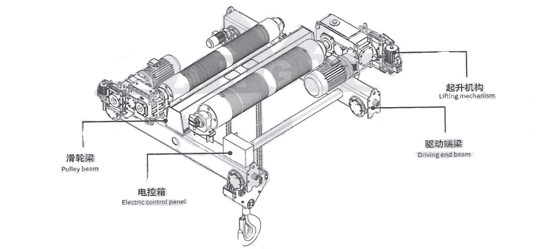
- ► This double girder overhead crane mainly consists of the main frame, driving end beam, lifting trolley, bridge accessories, and electrical control system. The overall structure adopts the form of two main beams and two end beams, with the main beam sitting on the rectangular structure end beam and connected by high-strength bolts. The main beam is a biased box structure, and the trolley rail is square steel. The main beam on the transmission side is equipped with a walkway for placing electrical equipment and maintenance.
- ► The lifting trolley of adopts open winch or C-type electric hoist with integrated design of motor, reducer, brake, drum and lifting limit switch, compact structure.
- ► The driving end beam adopts a three in one structure, with variable frequency speed regulation
- ► The trolley power supply can be divided into two forms: energy chains or cable pulleys.
- ► The operation mode is cable button, remote control, or driver's cab.
- ► Crane power supply can be safety sliding wires, mobile cables, or angle steel sliding wires.
-
Figure 2-1 Crane outline drawing
2.2 Lifting trolley
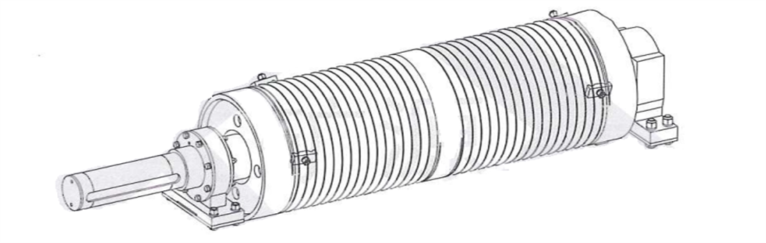
2.2.1 Electric open winch type
Double girder overhead crane's lifting mechanism consists of an integrated design consisting of a motor, reducer, brake, drum, pulley block, wire rope, lifting hook, lifting limit and overload limiter, etc., and is installed with three support points. The two ends of the drum are directly supported on the driving end beam of the trolley, and the hollow shaft reducer is connected to the extended drum shaft. The input shaft base is supported on the trolley frame through positioning bolts, achieving the fixation and torque balance of the reducer. The double shaft fixed pulley block is placed in parallel in the pulley beam, and the pulley beam connects the end beams on both sides with bolts to form an I-beam structure.
The motor is directly connected to the reducer, and the brake is installed on the outer side of the reducer.
Figure 2-2 Electric open winch trolley
- 1. Lifting motor
Double girder overhead crane's lifting motor is a three-phase asynchronous motor with variable frequency speed regulation for lifting and metallurgical purposes, which can achieve a fast and slow speed of 1:10. Optimized air-cooled, with F insulation level, IP54 protection level, and 40% on load factor.
The determination of the rated parameter value of the motor is based on the working environment temperature not exceeding 40℃ and the altitude not exceeding 1000 meters. When environmental factors change, they can affect the motor characteristics, please consult the manufacturer for specific changes.
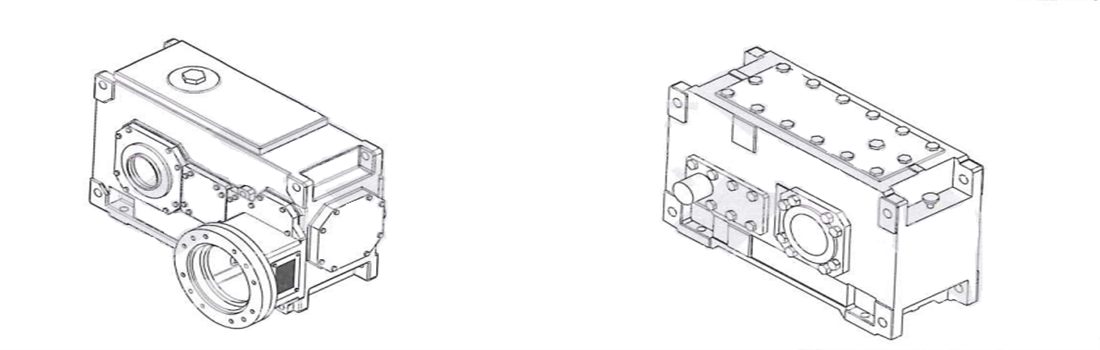
- 2. Lifting reducer
Double girder overhead crane's lifting reducer is composed of multi-stage gear transmission through Case-hardening and high-precision grinding treatment. It is arranged parallel to the shaft. The output shaft is hollow shaft, and the shell is welded. The double girder overhead crane's input shaft is divided into two types: flange type and cylindrical type.
Figure 2-3 reducer
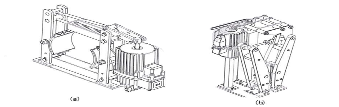
- 3. Lifting brake
Normally closed electric hydraulic brake, which opens when powered on and closes when powered off. It is installed on the high-speed shaft of the working mechanism to reduce braking torque. Special functions such as automatic compensation for pad wear, manual release, and opening/closing limit can be included. According to the construction form, there are two types of structures: wheel type (Figure 2-4a) and disc type (Figure 2-4b).
Figure 2-4 brake
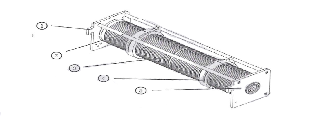
- 4. Drum device
Double girder overhead crane's drum is made of roll up steel plate and welded with a short shaft cylinder structure. Both ends are equipped with bearing seats, and one side extends out of the sleeve shaft. The surface of the drum is machined with spiral rope grooves and equipped with pressure plates for fixing the steel wire rope.
Fig. 2-5 Drum
- 5. Pulley block
Double girder overhead crane's pulley block is used for guiding and balancing the branch tension of wire rope, and is made of steel plate rolling. Adopting a dual axis fixed pulley structure, placed inside the pulley beam.
Fig. 2-6 Pulley block
1-bearing 2-retaining ring 3-dust cover 4-spacer 5-shaft end baffle 6-fastening bolt 7-pulley 8-shaft
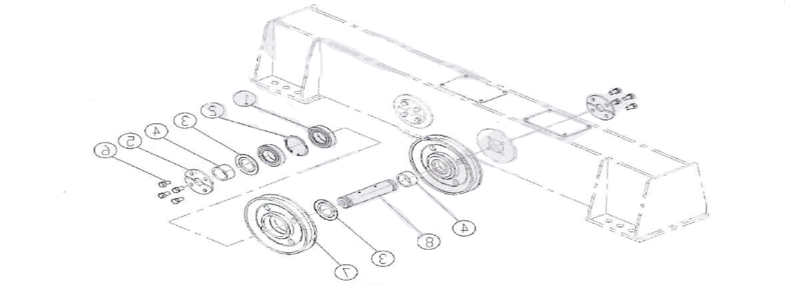
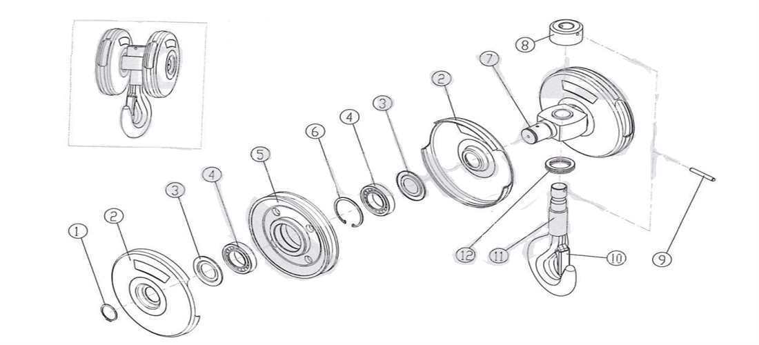
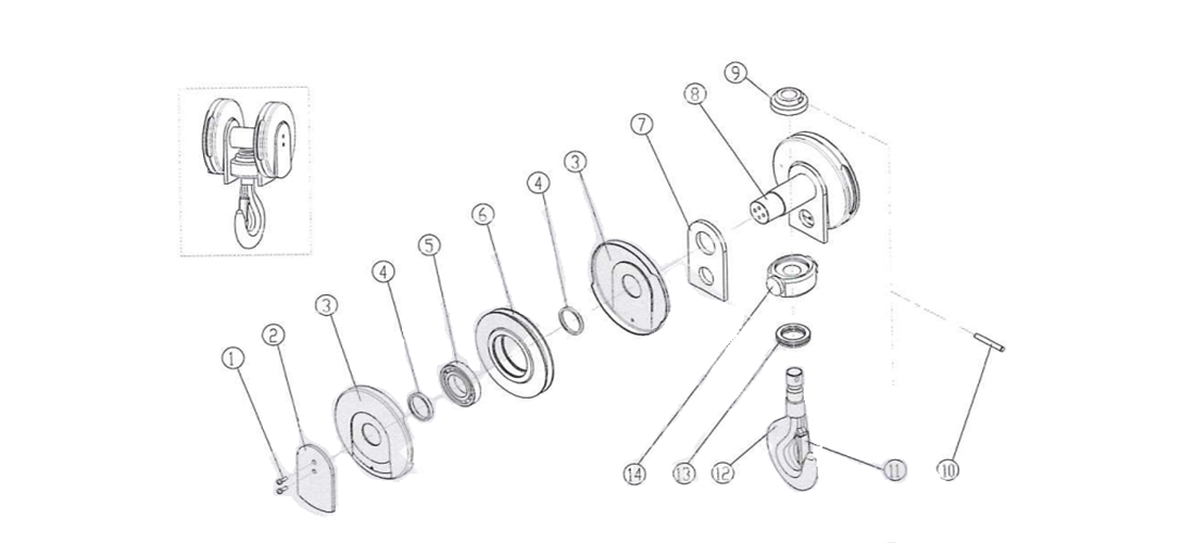
- 6. Hook block
Double girder overhead crane's hook block is the most commonly used lifting device on cranes, consisting of straight handle hooks, nuts, thrust bearings, crossbeams, pulleys, pulley shafts, and choke plates. The hook handle is threaded for installing nuts to secure the hook. The crossbeam is equipped with thrust bearings that allow the hook to rotate freely. In order to prevent the wire rope from unhooking, a safety card is installed at the hook mouth to prevent unhooking.
The hook is forged with DG35CrMo steel, and the small tonnage is a single shaft pulley structure (Figure 2-7). The pulleys are directly installed on both sides of the crossbeam. The large tonnage is a dual axis pulley structure (Figure 2-8), with pulleys arranged between the upper triangular plates on both sides, and hooks fixed to the lower part of the large plate through crossbeams.
Fig. 2-7 single shaft hook block
1-retaining ring 2-pulley half cover 3-dust cover 4-bearing 5-pulley 6-retaining ring
7-crossbeam 8-nut 9-pin 10-safety card 11-hook 12-bearing
Fig. 2-8 Double shaft hook block
2.2.2 Electric hoist type
Double girder overhead crane's lifting mechanism consists of a dual speed motor, a hard toothed reducer with an aluminum alloy casing cover, drum, wire rope, hook, and lifting limit switch. Integrated and compact design, adopting a C-shaped layout where the electric motor and the drum are arranged in parallel, that is, the electric motor and the drum are arranged in parallel, and fixed on the driving end beam by a pulley beam.
Figure 2-9 Electric hoist type trolley
- 1. Lifting motor
Double girder overhead crane's lifting motor is a dual winding squirrel cage pole changing motor, achieving a fast and slow speed of 1:6, and there is also an optional variable frequency motor. The motor casing is made of aluminum alloy, and a fan is installed at the end to enhance the cooling effect. The dual speed (variable frequency) lifting motor is equipped with 6 (3) thermistors or sensors, and the designed insulation level of the motor reaches Class F. If the temperature reaches the maximum limit of 150℃, the thermistor or sensor will cut off the power supply to the motor. When the temperature drops to normal operating temperature, the motor power supply will be reconnected.
The determination of the rated parameter value of the lifting motor is based on the working environment temperature not exceeding 40℃ and the altitude not exceeding 1000 meters. When environmental factors change, it will affect the characteristics of the motor. Please consult the manufacturer for specific changes.
The lifting motor is integrated with a double disc electromagnetic disc brake, and the braking times can reach 1 million, which requires no maintenance during the safe service life. Normally closed design, when the motor is powered off, the brake will automatically close to prevent the load from slipping. The brake clearance does not need to be manually adjusted after the first setting (the clearance can be adjusted by the brake spring). The specific reference values for inspection and adjustment are shown in Table 2-1
| I beam rail model GB/T706 |
Rated lifting capacity(t) |
| 0.5~1 |
2~3 |
5~10 |
16~20 |
| 16 |
0 |
|
|
|
| 18 |
2 |
| 20a |
3 |
0 |
| 20b |
4 |
1 |
| 22a |
6 |
3 |
| 22b |
| 25a |
7 |
4 |
0 |
| 25b |
8 |
5 |
1 |
| 28a |
9 |
6 |
2 |
| 28b |
| 32a |
|
8 |
4 |
| 32b |
| 32c |
9 |
5 |
| 36a |
5 |
| 26b |
10 |
6 |
6 |
| 36c |
| 40a |
11 |
7 |
7 |
| 40b |
| 40c |
12 |
8 |
8 |
| 45a |
13 |
9 |
9 |
| 45b |
| 45c |
14 |
10 |
10 |
| 50a |
|
11 |
11 |
| 50b |
|
11 |
11 |
| 50c |
|
12 |
12 |
| 56a |
|
13 |
13 |
| 56b |
|
13 |
13 |
| 56c |
|
14 |
14 |
| 63a |
|
15 |
15 |
| 63b |
|
16 |
16 |
| 63c |
|
16 |
16 |
- 2. Lifting reducer
Double girder overhead crane'se lifting reducer is composed of multi-stage gear transmission through Case-hardening and high-precision grinding, and the output shaft is designed with involute splines.
The shell is made by aluminum alloy material, which is lightweight and corrosion-resistant. The fully sealed semi fluid grease inside the box allows all gears to receive sufficient lubrication without the need to replace the lubricating oil during the designed safe use cycle.
Fig. 2-10 Lifting reducer
- 3. Drum device
Double girder overhead crane's drum is made by seamless steel pipes and is connected to the motor's spline shaft through a spline sleeve on one side to transmit torque. The surface is machined with spiral rope grooves. The drum is equipped with a rope guide, made by wear-resistant engineering plastic, with a rope groove on the inner side. During assembly, attention should be paid not to tighten the bolts too tightly, otherwise they will lose elasticity.
The rope guide bracket moves along the connecting rod during the rotation of the drum to maintain the correct position of the rope guide on the drum.
Fig. 2-11 Drum
1-left plate 2-connecting rod 3-drum 4-rope guide 5-right plate
- 4. Hook device
Double girder overhead crane's hook block is composed of straight shank hooks, nuts, thrust bearings, crossbeams, pulleys, pulley shafts, and choke plates. The hook handle is threaded for installing nuts to secure the hook. The crossbeam is equipped with thrust bearings that allow the hook to rotate freely. In order to prevent the steel wire rope from unhooking, a safety card is installed at the hook mouth to prevent unhooking.
Fig 2-12 Electric hoist hook block
1-fastening bolt 2-pressing plate 3-pulley cover 4-spacer 5-bearing 6-puliey 7-yoke plate
8-axis 9-hook nut 10-pin 11-safety card 12-hook 13-bearing14-hook beam
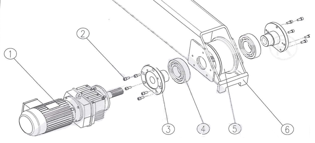
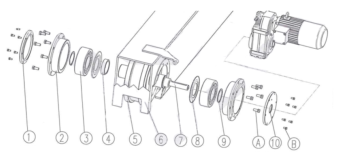
2.3 Driving end beam
- ► The driving end beam is composed of a three in one reducer, wheel group, and end beam, with a modular design.
- ► The standard configuration of the motor has a F insulation level and IP54. protection level.
- ► The motor is integrated with an electromagnetic disc brake.
- ► Equipped with elastic buffer and anti-derailment device.
There are two forms of driving end beams:
- 1)Spline shaft form - The bearings are arranged inside the wheels, and the reducer is fixed on the end beam web through a support frame. The output spline shaft drives the wheels, which in turn drives the entire crane to run along the track direction.
- 2) Hollow shaft form - The reducer is a flat key hollow shaft form, which is installed on the wheel shaft and drives the wheel to rotate. The wheel block is fixed to the end beam web plate through a circular bearing box and fixed with bolts. The bearing adopts self-aligning bearings, which can adjust the contact between the wheel and the track.
Figure 2-13 Spline shaft form
1-3 in 1 reducer 2- Bolt 3- Supporting frame 4- Axis 5-Wheel6-Anti-releasing plate
Figure 2-14 Hollow shaft form
Cover 2. Bearing housing 3. Self-aligning bearing 4. Spacer bush 5. Wheels 6. Thread-off-proof plate 7. Wheel axle8.Dust cap
9. Check ring 10. Through cover A,B. Fastening bolt
2.4 Electric control system
Double girder overhead crane's electric control system consists of an electric control box, limit switch, handheld controller (ground operation) or driver's cab (air operation), and electrical components. It has functions such as phase sequence voltage loss, short circuit, limit, emergency stop, and overload protection.
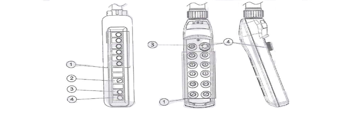
The handheld controller is used to control the lifting, lowering, trolley travelling, and crane bridge travelling. It is divided into two types: suspended flashlight or remote control. When multiple control methods such as manual switch+remote control or cab+remote control are used, interlocking function is provided to ensure that only one control method is effective at any given time.
Figure 2-15. Suspended flashlight
The control voltage of the flashlight or remote control is 48V. According to the direction symbol shown on the pendant, press the button correctly, and control the action of the crane through the opening and closing of the relay in the electric control box.
When the crane is operated by the driver's cab, there is an operating console in the driver's cab, which is equipped with devices such as operating handles and function buttons.
.png)
Figure 2-16 QTA series Combination Control Console
The lifting limit switch is a worm gear and worm structure, installed at the end of the drum to limit the position of the lifting hook. The trolley adopts a cross type limit switch for cross travelling, which has a two-stage limit function of deceleration and stop.
Figure 2-17 Cross travelling limit switch
Double girder overhead crane's long travelling limit switch adopts photoelectric switch, which reduces the crane travelling speed to slow down and to zero before the crane collides with the bumper, equipped with a reflective plate.
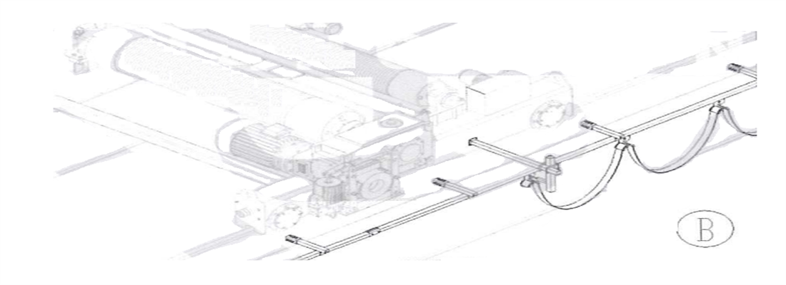
Trolley power supply adopts energy chain or cable pulley.
A--Energy chain: Install a drag chain device on the walking platform of the transmission side, fixing the cable in the engineering plastic material drag chain, and moving back and forth along the guide groove as the trolley moves.
Figure 2-18 Energy chain
B--Cable pulley: refers to the flexible flat cable introduced through a suspended cable pulley, using the C-shaped steel arranged on the passive side of the crane as a slide to move with the trolley. The towing cable adopts YVFB flat cable.
Figure 2-18 Cable pulley
The electrical connection adopts the international standard heavy-duty aviation plug, with a protection level of IP65, which has the characteristics of fast insertion and removal, reliable connection, etc.
The electric control box is placed on the railing of the walkway.
2.5 Technical Characteristics
2.5.1 Main technical parameters
See attached drawings for details
2.5.2 Overall dimensions and weight
See attached drawings for details
3. Double Girder Overhead Crane safety regulations
3.1 Basic principles
- ► Operators must undergo sufficient training and obtain certificates issued by relevant national departments before they double girder overhead crane work.
- ► The operator must carefully read and master the relevant content in this manual and GB6067.1 "Safety Regulations for Cranes".
- ► This manual should be placed in a place where the operator can read it at any time.
3.2 User Instructions
- ► Users should ensure that the operation and maintenance personnel strictly follow the relevant regulations of the national labor and safety protection department during the work process. The following information is crucial for ensuring double girder overhead crane's safety and its operation and maintenance personnel:
- ► Users must confirm that the crane has undergone professional inspection and testing before initial trial operation and before re operation after major repairs
- ► The user must confirm that the crane is inspected and tested by professional personnel at least once a year.
- ► Users must keep all results and records during Double girder overhead crane's inspection and testing process.
- ► The crane should be operated by a dedicated person, and the operator must fully grasp the relevant knowledge in installation, maintenance, and operation instructions
- ► Users should ensure that side pulling does not occur during operation.
- ► Users should ensure that they do not lift loads exceeding the rated lifting capacity
- ► Before each shift handover, the operator must check whether the braking device is in good condition.
- ► When the operator discovers obvious defects in Double girder overhead crane, they must immediately stop using it and notify the relevant maintenance personnel
- ► Users should ensure that there is no load hanging on the hook for a long time when double girder overhead crane is not in use.
- ► The operator should ensure that the load can be safely lifted and that there are no idle personnel in the lifting area.
- ► Maintenance personnel must carry out maintenance work with the main power supply turned off.
3.3 Personnel requirements
- ► In order to prevent accidents caused by unqualified personnel operating equipment, users should establish complete personnel qualification limits. Establish a detailed division of responsibilities for drivers, maintenance personnel, service personnel, etc., allowing only work within their respective scope of responsibility, and strictly prohibiting cross responsibility work. The following are the personnel qualification restrictions proposed for users:
- ► The personnel reliability is a fundamental condition for working on this equipment.
- ► The reliability of personnel is a fundamental condition for working on this equipment.
- ► It is necessary to ensure that all staff members meet the required legal minimum working age.
- ► Drivers must undergo professional training and pass the qualification before being allowed to operate the double girder overhead crane. Only one driver is allowed to operate the equipment per shift. The driver should carry the key of the main control switch with them and should not transfer it to others for safekeeping or misplace it at will.
- ► Only qualified personnel who have received training can engage in related work on double girder overhead crane.
- ► During the training process, special emphasis should be placed on the safety measures training required for hazards and safety.
- ► Personnel qualifications must be regularly reviewed annually.
- ► The responsibilities to operating personnel and maintaining personal must be clearly defined.
- ► Designate a device manager and clarify their responsibilities, allowing them to refuse instructions from third parties that violate safety operations.
- ► The labor division for various personnel is shown in Table 4-1 (√ indicates allowed, X indicates not allowed).
| Table 3-1 Labor division |
| Job classification |
Trained personal |
Qualified technician |
Qualified electrician |
After sales service personnel |
| Equipment operation |
√ |
× |
× |
× |
| Troubleshooting |
× |
√ |
√ |
√ |
| Mechanical fault maintenance |
× |
√ |
× |
√ |
| Electrical troubleshooting |
× |
× |
√ |
√ |
| Routine maintenance and repair |
× |
√ |
√ |
√ |
3.4 Injury risk
- ► Incorrect use.
- ► Insufficient maintenance and upkeep.
- ► Failure to carefully read the safety instructions provided in the instructions may result in injury.
- ► Unauthorized inspection, maintenance, and crossing on the crane without cutting off the main power supply may cause personnel to fall.
- ► Wearing loose clothes, jewelry, etc. may be involved.
- ► Failure to observe when lift the hook to the upper limit position may cause it to hit the ceiling.
- ► Taking nicotine, alcohol, or drugs can affect reaction ability, and personnel in this state cannot operate thedouble girder overhead crane.
- ► When using ground control, the operator did not maintain a safe distance from the lifted object.
3.5 Hazardous areas
The installation and maintenance personnel must understand double girder overhead crane dangerous area to avoid personal injury and death. See the following table for dangerous working area of crane.
| Table 3-2 Crane hazardous working area |
| Hazardous area |
Specific parts |
Matters needing attection |
| Areas with a damage risk |
Lifting mechanism |
Pay attention to the lifting mechanism during travelling |
| Main and auxiliary hook |
Pay attention to the main and auxiliary hook devices during travelling |
| Inclined ladder leading to component |
Pay attention to the travelling mechanism during travelling |
| Areas with fall hazards |
Platform edges near railings of r each platform |
Holding up the railing |
| Areas with risk of electric shock |
Transformer room, electrical room and electrical cabinet, external electrical components, crane sliding wires |
Do not touch electrical components |
| Hazardous areas withfammable materials |
Around the lubricating pump |
Smoking and open fire are prohibited. Checkwhether the line is aging regularly |
During double girder overhead crane's operation, personnel are prohibited from staying in the following hazardous areas:
- ► Trolley travelling area
- ► The lifting mechanism working area;
- ► Below the working area of the main and auxiliary hooks
- ► Crane travelling area
3.6 Violation (not limited to the following situations)
- ► The load exceeds the rated lifting capacity.
- ► Side pulls during loading.
- ► Lifting or transporting personnel.
- ► Frequent jogs.
- ► The wire rope has protrusions, broken strands, or other damages but has not been replaced.
- ► Deliberate operation to trigger emergency switch.
- ► Continue to operate even there is unnormal phenomenon or abnormal noise.
3.7 Before operation
The operator shall inspect the motor, brake, steel wire rope, safety device and other components according to the daily inspection requirements, and if any abnormalities are found, they shall be eliminated. If there are windproof devices such as rail clamps, they should be lifted.
.png)
--Only when all safety devices are in their normal installation position and working properly. the crane can be started.
-- Ensure that double girder overhead crane does not harm anyone when starting.
3.8 During operation
- ► When lifting for the first time in each shift (or when the load reaches its maximum rated lifting capacity), after lifting to 0.5 meters above the ground, the object should be lowered again to check the brake performance, only confirm it is reliable, can proceed normal operations.
- ► Operations should be carried out according to unified command signals.
- ► Prohibit using the crane limit switch to stop the double girder overhead crane.
- ► It is prohibited to use one crane to push another crane.
- ► It is strictly prohibited to pass over the human body when lifting objects.
- ► No one is allowed to cross from one crane to another.
- ► The operator should closely monitor the travelling direction and the personnel presence or obstacles in its vicinity.
- ► The crane controller should be started step by step. When the mechanism is not completely stopped, it is prohibited to reverse the controller from the forward position to the reverse position directly for braking.
- ► When lifting, hands should not be held between the rope and the lifting object.
- ► When lift the lifting appliance, it should be prevented from hitting the top.
- ► If there is an abnormal situation, press the emergency stop button to disconnect the main circuit power supply.
- ► The stopping block at both ends of the rail are only used as limit when there is accident and should not be collided frequently during daily operations.
- ► If the wire rope is found to be loose or tangled, it should be lowered to loosen the wire rope and then rewound
3.9 After operation
- ► Raise the lifting appliance to a position close to the highest point, park the crane at the designated position, set the control handle to the zero position, and cut off the main power supply.
- ► Move the cable pendant (if any) to the end of the double girder overhead crane and cut off the power supply.
- ► Cut off the power supply of the remote control (if any) and place it in the designated position.
- ► The outdoor crane should set up the rail clamp.
- ► Perform crane daily maintenance.
- ► Do a good job in handover work.
3.10 Safety devices
Safety devices are necessary component to prevent crane accidents, including: devices to limit crane’s travelling and working position, devices to prevent crane overload, interlocking protection devices, etc. According to different requirements, double girder overhead crane is equipped with the following devices:
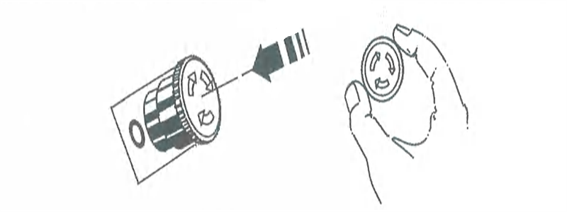
3.10.1 Emergency stop button
Mushroom shaped emergency stop buttons are installed on the cable pendant, remote control, or console. During operation, if there are any unexpected situations such as lifting, trolley or bridge not following the instructions, or other unexpected situations, the [Emergency Stop Button] can be pressed to stop all actions, and then the cause can be investigated.
- ► Press the red emergency stop button=>Cut off the power supply of crane main circuit
- ► Rotate the emergency stop button clockwise=>Release the button to start crane.
-
Figure 3-1 Emergency stop button
3.10.2 lifting limit switch
The lifting limit adopts a worm gear structure and is installed at one end of the rolling mill. The switch is equipped with four contacts for precise phase sequence control, which decelerates first and then stops, allowing the crane to gradually reach the upper and lower limit positions at a slow speed, thereby cutting off the power circuit and stopping the motor, effectively protecting the safety of operation.
Figure 3-2 Lifting limit switch
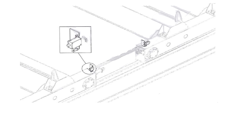
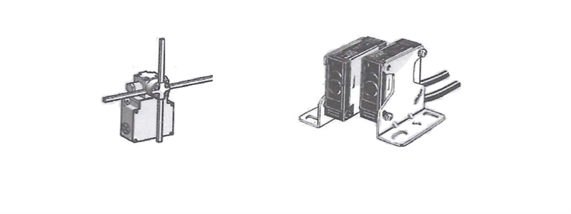
3.10.3 Cross travel limit
The trolley adopts a cross shaped limit switch for travelling, with secondary limit functions: deceleration and stop.
Figure 3-3 Cross shaped limit switch
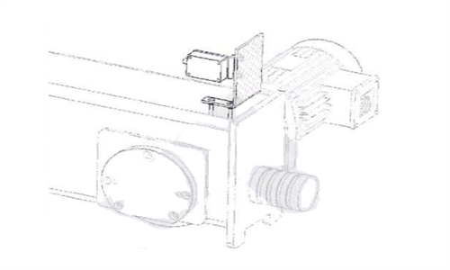
The crane bridge travelling limit adopts a photoelectric switch, which reduces the crane’s travelling speed to slow down and to zero before crane collides with the bumper. Equipped with a reflective plate.
Figure 3-4 Photoelectric switch
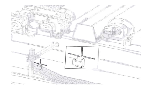
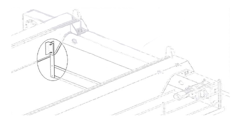
3.10.4 Anti-collision device (optional)
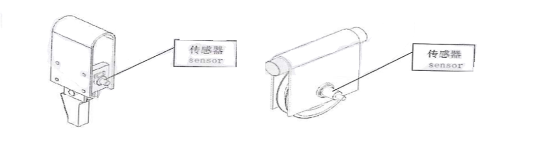
According to the requirements, the crane can be equipped with photoelectric anti-collision devices to prevent multiple cranes from colliding with each other on the same rail. The layout is shown in Figure 4-6. When two cranes are close to a certain safety distance, the light wave sent by A crane transmitter is received by B crane receiver. An electrical signal is generated through the Phototube. After the waveform is shaped and amplified, the relay acts, the buzzer gives an alarm and automatically cuts off operating mechanism’s power supply.
Two adjacent cranes should be equipped with one set each, interacting with each other. The commonly used photoelectric anti-collision devices include laser anti-collision devices and infrared anti-collision devices, their installation and maintenance can be found in the accompanying user manual.
Figure 3-5 Anti-collision device
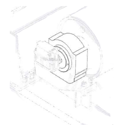
3.10.5 Overload limiter
The overload limiter for electric open winch type is in the form of a bearing seat, installed at the end of the drum. When the load exceeds the rated lifting capacity, it will prevent the lifting action, thereby providing safety protection.
Figure 3-6 Overload limiter for electric open winch
The electric hoist type overload limiter will prevent the lifting action when the load exceeds the rated load, thus providing safety protection. Overload protection is achieved through electronic load sensors. The following figure shows the installation forms of overload limiters for single rope winding and double rope winding, respectively.
Figure 3-7 electric hoist type overload limiter
- --The overload limiter has been verified for rated load before leaving the factory. When conducting overload tests on site, the overload limiter should be shielded and restored after the test is completed.
- --If there is a significant difference between the set value and the actual situation, please contact the manufacturer or qualified maintenance technicians to reset the overload limiter.
3.10.6 Buffer and rail cleaner
Both bridge frame travelling mechanism and trolley travelling mechanism are equipped with pouring rubber elastic buffer, which can alleviate the impact when crane bridge or trolley move to the final stop or when two cranes collide with each other, effectively absorbing collision energy.
Rail cleaner is installed in front of the running wheels, 10mm away from the rail surface, which can remove obstacles accumulated on rail.
Figure 3-8 Buffer and rail cleaner
-
3.10.7 Sliding wire protection device
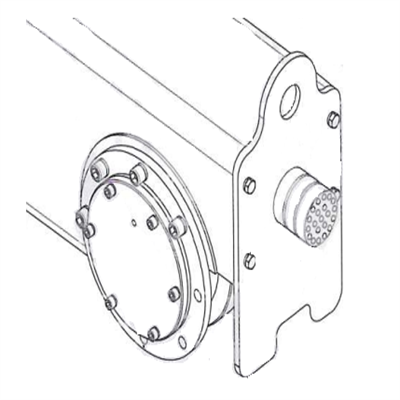
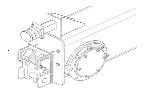
The power supply sliding wire side is equipped with blocking hook frame, which can prevent the lifting appliance or wire rope from touching the sliding wire due to shaking when the trolley runs to the end limiting position.
Figure 3-9 Blocking hook frame
3.10.8 Sliding wire maintenance device
When double girder overhead crane's power supply is not on the same side of the driver's cab, a maintenance cage is needed to install sliding wire side, arranged below walkway of the transmission side, and equipped with a crane conductive frame. When a malfunction occurs, maintenance personnel can enter the cage through the access hole on the walking platform for maintenance work.
Figure 3-10 Maintenance cage3.10.9 Protective railing
Railing is installed at the walkway and passage, with a height of 1050mm and three horizontal bars. The lower part of the railing has a kick board.
3.10.10 Wind proof device
The outdoor double girder overhead crane is equipped with a manual flip plate rail clamp, which is installed at the end of the driving end beam. When the crane is working normally, the rail clamp is retracted; When strong wind comes, the crane stops working, and the operator puts down the clamp to clamp the rail to prevent the crane from sliding.
-
Figure 3-11 Manual rail clamp
3.10.11 other protection
In addition, the crane is also equipped with various electrical protections:
- ► Overcurrent protection - Each mechanism's motor is equipped with a separate two-phase overcurrent relay, and the other phase is protected by a total overcurrent relay inside the protection box. The operating current of each relay is 2.5 times of the total rated current of the protected motor.
- ► Line protection - All external lines have short-circuited or grounding protection.
- ► Voltage loss protection - When the power supply is interrupted, all electrical equipment that involves safety should not be automatically turned on, should be in a power off state to avoid the mechanism acts on its own after the power supply is restored.
- ► Zero position protection (available during cab operation): If the operation is stopped due to a fault or voltage loss, after the power is supplied again, the mechanism cannot act on its own. Only by placing the control handle manually in the zero position and pressing the "start" button again, can the mechanism restart.
- ► Interlocking protection - both railing door and driver's cab door are equipped with door switches. When any door is opened, the power supply to the corresponding mechanism is immediately disconnected. When multiple control methods are used, each control point is interlocked with each other to ensure that only one control point is in operation at any time, and each control point is equipped with an emergency power outage device.
- ► Running alarm (optional) When the crane is running, the alarm emits a sound accompanied by a flashing light signal to remind personnel to pay attention
Special warning
►The purpose of this safety regulation is to prevent personal injury and reduce damage to double girder overhead crane and on-site facilities.
►For you and others’ personal safety, as well as the safety of cranes and on-site facilities, please strictly comply with this safety regulation
- ►Our company is not responsible for personal injury, damage to cranes and on-site facilities caused by violation of this safety regulation.
.png)
.png)
.png)