1.Product overview
1.1 Characteristics and types
Electric single girder overhead crane (hereinafter referred to as crane) is a widely used lifting machinery, with an electric hoist as the lifting mechanism. It can load, unload, and transport materials and equipment intermittently and repeatedly in general working environments, can vertical lifting, longitudinal and lateral movement functions. The load handing device is a hook or other specialized lifting device to meet the needs of users for lifting various types materials. Work levels from A3 to A6.
According to the position and operation mode of the lifting mechanism, it can be divided into:
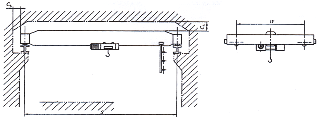
- ♦ The electric hoist trolley runs on the lower flange of the main girder, equipped with standard building height trolley, as shown in Figure 1-1a
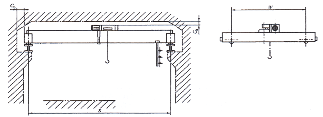
- ♦ A electric single girder overhead crane equipped with a headroom electric hoist, as shown in Figure 1-1b;
- ♦ Electric single girder overhead crane with an electric hoist is installed on an angle shaped trolley, as shown in Figure 1-1c.
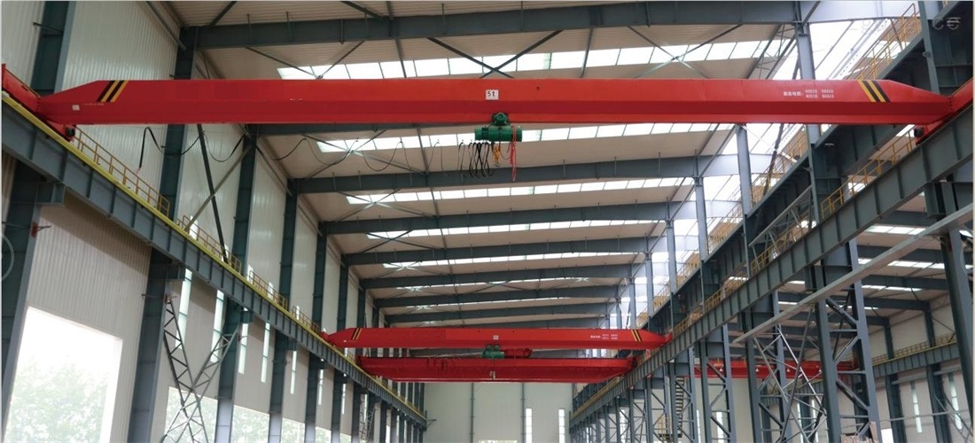
Figure 1-1a Outside View of the Crane
Figure 1-1b Outside View of the Crane
Figure 1-1c Outside View of the Crane
According to different load handing device and working environments, they are divided into the following types:
| Table 1-1 Crane type |
| Mode |
Name |
Characteristics |
| LD |
Electric single girder overhead crane |
The main girder is welded with a U-shaped box structure and ordinary hot-rolled I-beam to form a box shaped solid web girder, which is suspended on the I-beam of the main girder, using an electric hoist as the lifting mechanism. Most of them are large lifting capacity cranes. |
| LDA |
Electric single girder overhead crane |
The main girder is welded with a U-shaped box structure and ordinary hot-rolled I-beam to form a box shaped solid web girder, which is suspended on the I-beam of the main girder, using an electric hoist as the lifting mechanism. Most of them are small lifting capacity cranes. |
| LDE |
Double hoist electric single girder overhead crane |
The structural is the same as LD type crane, with two electric hoists arranged, which have the functions of lifting and lowering simultaneously and lifting and lowering separately. It is suitable for simultaneously lifting materials of different lengths, such as pipes and bars. |
| LDC |
Electric single girder overhead crane |
The electric hoist is in a low clearance form, main girder is box weld structure and a lower flange plate as the running rail for electric hoist.. The rest are the same as LD crane. |
| LDP |
Leaning suspension electric single girder overhead crane |
Electric hoist is installed on an angle shaped trolley as a lifting mechanism. The angle shaped trolley is arranged in a leaning suspended manner on one side of the box shaped main girder to run. The trolley is equipped with upper and lower horizontal wheels, which are arranged in three points with the vertical walking wheel. The position of the electric hoist is raised from traditional lower side of the main girder to the upper side of the main girder, effectively improving the lifting height. |
| LDPE |
Double hoist leaning suspension electric single girder overhead crane |
Two angle shaped trolleys are used as the lifting mechanism, arranged in a leaning suspended manner on one side of the main girder for operation, with the function of raising and lowering at the same time or operating separately. The rest are the same as LDP type cranes. |
| LDZ |
Electric single girder overhead grab crane |
The lifting mechanism adopts a electric hoist type four rope grab bucket, which is used to grab loose materials. The basic structure of this type of crane is the same as that of the LD type crane |
| LDY |
Electric single girder overhead crane for handling molten metal |
This type of crane is an improved product based on LD type crane, which uses an electric hoist as the lifting mechanism for lifting molten metal. It is equipped with multiple safety protection devices and has a working level of A6. |
| LX |
Suspension electric single girder overhead crane |
Crane long travel rail adopts I-shaped steel or H-shaped steel, fixed on the upper part of the factory building. The main girder is welded with a U-shaped groove and ordinary hot-rolled I-shaped steel to form a box shaped solid web girder. Electric hoist is used as the lifting mechanism, and the main girder and end girder are connected by a pin shaft, suspended below the crane rail for operation on the ground. |
1.2 Product specification
1.2.1 Commonly used lifting capacity series
| Table 1-2 Lifting capacity series |
| Load handing device |
Crane lifting capacity series(t) |
| Hook |
Single hook |
0.5; 1; 2; 3; 5; 10; 16; 20; 25; 32 |
| Double hoist |
with same lifting capacity |
0.5+0.5; 1+1; 2+2; 3+3; 5+5; 10+10; 16+16; |
| with different lifting capacity |
The lifting capacity of the electric hoist should comply with the single hoist lifting capacity series, and the total lifting capacity should not
exceed 32t |
1.2.2 Commonly used span series
| Table 1-3 Commonly used crane span S(m) |
| 7.5 |
8 |
10.5 |
11 |
13.5 |
14 |
16.5 |
| 17 |
19.5 |
22.5 |
25.5 |
28.5 |
31.5 |
- |
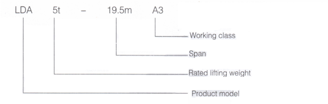
1.3 Mode expression method
1.4 Ambient condition
- 1.4.1 Electric single girder overhead crane generally are operated indoors, with a working environment temperature of -20℃~+50℃ and the relative humidity is no more than 85% (at an ambient temperature: +25 ° C);
- 1.4.2 The elevation of crane’s installation and use site shall not exceed 1000m (if it exceeds 1000m, the capacity of the motor shall be checked, and if it exceeds 2000m, the capacity of the electrical components shall be checked);
- 1.4.3 There must be no flammable, explosive, corrosive gases or flammable, explosive dust in the working environment.
Note: If the above range is exceeded, it shall be resolved through negotiation between the user and the manufacturer
1.5 Operating condition
1.5.1 The power supply is three-phase AC (three-phase four wire system), with a rated frequency of 50H or 60Hz. The rated voltage is 220V~660V, and the upper and lower limits of allowable voltage fluctuations on motors and electrical control equipment are ± 10%.
1.5.2 The electric single girder overhead is installed on a dedicated rail beam and runs along the rail to lift items. The rail laying should be carried out in accordance with GB/T 10183.1 "Tolerances for Crane Wheels and Crane and Trolley Tracks - Part 1: General Provisions" and meet the following requirements:
- ♦ 1) Rail span deviation: 3-10mm
- ♦ 2) Rail top elevation difference: 10mm
- ♦ 3) Height difference of the same section rail:<10mm
- ♦ 4) Rail inclination: ≤ 1/1000mm
- ♦ 5) Joint gap: 1-2mm
1.5.3 Electric single girder overhead stops should be installed at both ends of the rail beam to prevent the crane from rushing out of rail.
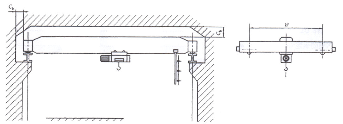
1.5.4 The minimum safety distance between crane and building should meet the following requirements: the upper clearance should be 200mm, and the side clearance should be ≥ 100mm
1.5.5 Grounding resistance value of the the running rail should not exceed 4MQ (to be the responsibility of the user).
1.6 Environmental impacts
During the installation, use, and maintenance process of this product, improper disposal may have an impact on the surrounding environment. The specific impact is shown below:
| Table 1-4 Impact on Environment |
| Item |
lmpact on Environment |
Preventative Measure |
| When installing, maintaining or disassembling |
A certain amount of solid waste will be generated during construction |
Disposal following local regulations |
| When lubricating oil leaks |
Cause soil and water pollution |
Check the leakage point and repair until no leakage is found |
| When replacing lubricating oil |
Pollute soil and water due to uncontrolled discharge |
Waste grease shall be collected in dedicated containers |
| When meshing points wear out severely |
Noise exceed the limits, influence the operator |
Calibrate, adjust or replace worn parts |
2. Structure characteristics
2.1 General introduction
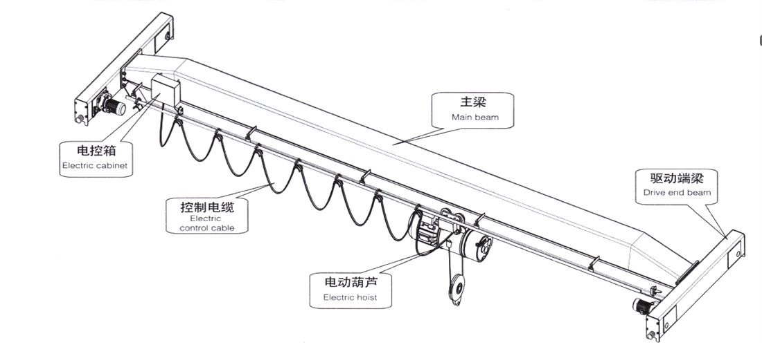
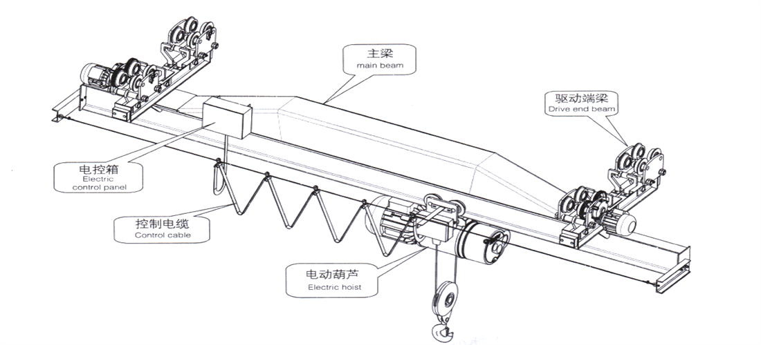
- ♦ The electric single girder overhead adopts a single main girder structure, with an electric hoist as the lifting mechanism, suspended on the lower edge of the main beam for travelling. The whole is composed of an electric hoist, a main girder, a driving end girder, and electrical equipment.
- ♦ The main beam is welded with a U-shaped box structure and ordinary hot-rolled I-beam to form a box shaped solid web girder, or a box shaped structure is adopted. The main girder is ♦ connected to the end beam with high-strength bolts or pins.
- ♦ The lifting mechanism adopts an electric hoist, which can move horizontally along the main girder.
- ♦ Operation mode is remote control , button manual switch or driver's cab.
- ♦ Power feeding of the trolley (electric hoist) adopts the cable pulley. Electric single girder overhead power feeding includes safety sliding wire, seamless sliding wire, and cable pulley.
-
Figure 2-1 LDA type electric single girder overhead
Figure 2-2 LX type suspension electric single girder overhead
2.2 Lifting mechanism
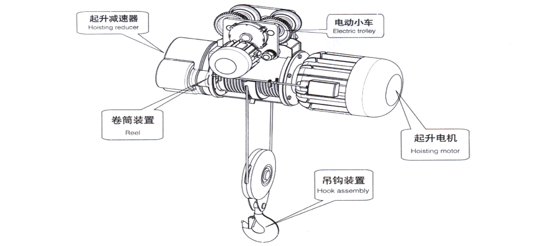
2.2.1 General electric hoist
The lifting mechanism adopts CD (single speed) and MD (double speed) electric hoists, which have vertical lifting and running functions. It consists of lifting motor, reducer, drum device, hook device, electric trolley, and electric control box. The lifting motor, drum device, and reducer are arranged in series, and the specific structural form is detailed in the relevant electric hoist manual.
Figure 2-3 Electric Hoist
2.2.2 Electric hoist for handling molten metal
This electric hoist is an improved product specially designed based on CD and MD models, with high-temperature insulation protection, double lifting limit protection, and M6 working level.
When the rated lifting capacity is greater than 5t, the electric hoist is equipped with not only a working brake, but also a safety brake at the low speed level. When the working brake fails or the transmission components break, it can reliably support the rated load. When the rated lifting capacity is less than or equal to 5t, the electric hoist is designed to be 1.5 times of the rated lifting capacity.
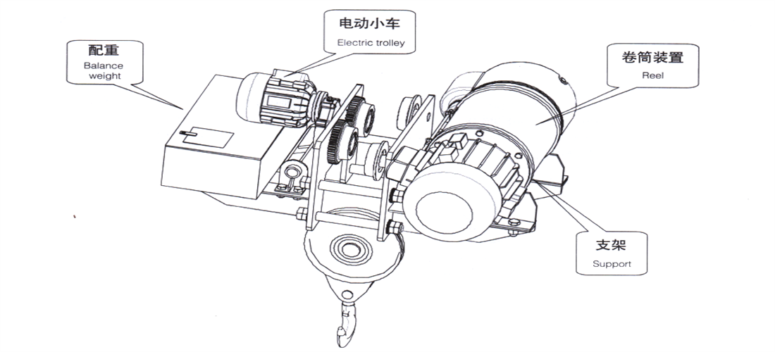
2.2.3 Headroom electric hoist
The headroom electric hoist is suitable for places with limit requirements for lifting height. It is based on the CD type hoist, with the electric trolley arranged in the middle, and the drum device and wire rope fixing device placed on both sides of the bracket to increase the lifting space of the hook.
To ensure balance on both sides and uniform wheel pressure, a counterweight is installed on the side of the electric trolley.
Figure 2-4 Headroom Electric Hoist
2.2.4 Angular trolley
The electric hoist is installed on an angle shaped trolley as a lifting mechanism. Angle shaped trolley is arranged in a leaning suspended manner on one side of the box shaped main girder for operation. The trolley is equipped with upper and lower horizontal wheels, arranged at three points with vertical walking wheels.
The installing position of the electric hoist is raised from the traditional lower side of the main girder to the upper side of the main girder, effectively improving the lifting height. To prevent trolley from tipping over, an anti tipping safety hook device is installed at the lower horizontal wheel.
Figure 2-5 Angular Trolley
2.3 Bridge travelling mechanism
The electric single girder overhead traveling mechanism is driven by a brake motor to drive the reducer, driving wheels to rotate and achieving longitudinal movement.
There are two ways:
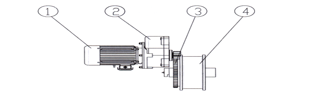
1) Open separate transmission: that is, two or four electric motors drive the circles on the wheels through reducers, causing wheels to rotate ( wheel shaft does not rotate);
Figure 2-6 Open separate Transmission
1-brake motor 2-reducer 3-gear ring 4-wheel
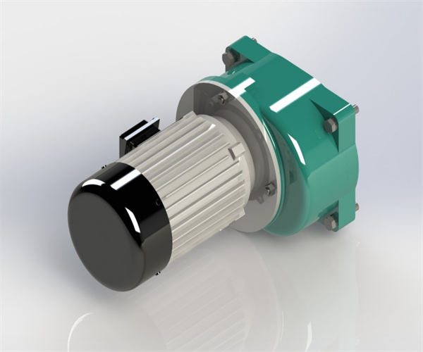
2) Closed three in one separate transmission: using 2 or 4 sets of three in one reducer motors to directly drive the wheels on both sides.
Figure 2-7 Closed three in one separate transmission
2.4 Bridge
2.4.1 The bridge is a box type single girder structure, consisting of the main girder, end girder, and accessories.
2.4.2 According to different lifting capacity, span, or model, the main girder is divided into four forms:
1) The pentagonal cross-section composite main beam (Figure 2-8a):
Molded and cold-formed 5-6mm steel plates into U-shaped channel steel, which are welded together through rib plates, side plates, and I-beams.
2) Pentagonal cross-section composite main beam (Figure 2-8b):
The U-shaped structure is formed by welding steel plates with varying thicknesses, and is welded together through rib plates, side plates, and I-beams.
3)Box shaped main beam (Figure 2-8c):
Made of welded steel plates, the lower flange plate of the main girder is wider and serves as the running rail for electric hoist.
4)Box girder (Figure 2-8d):
It is welded by steel plates, with running wheel rail laid above the main web, upper and lower flat wheel rail laid on both sides of the web, used for LDP type electric single girder overhead.
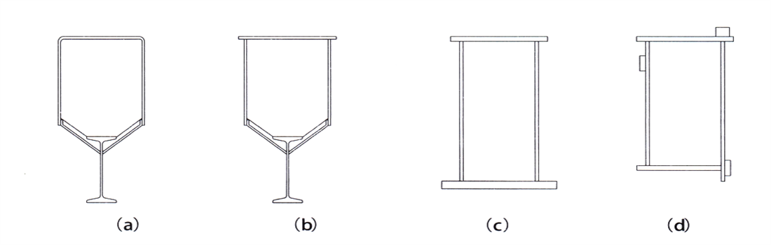
Figure 2-8 Main Girder Form
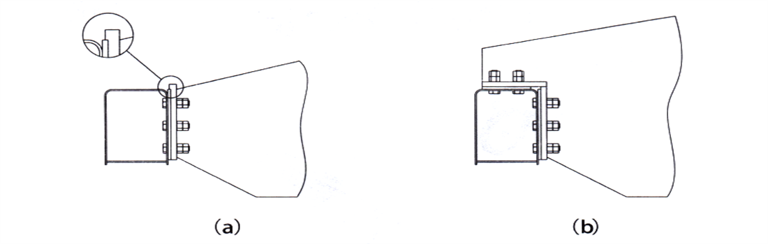
2.4.3 Depending on the model, there are different connection form between the main beam and the end beam:
1) Hanging connection (Figure 2-9a): The connecting surface of the main end girder is a processed connecting plate, which is connected with high-strength bolts and load-reducing flanges; The main girder flange’s connecting plate serves as a load-reducing structure, replacing the connecting bolts to bear shear force and is hung on the connecting plate on the end girder side.
2) Lap type connection (Figure 2-9b): When the lifting capacity or span is large, lap connection is adopted, which means that a part of the main girder end is carried on top of the end girder, and main girder end has vertical and horizontal connecting plates fixed to the end girder through high-strength bolts as a whole.
Figure 2-9 Connection of Main and End Girders
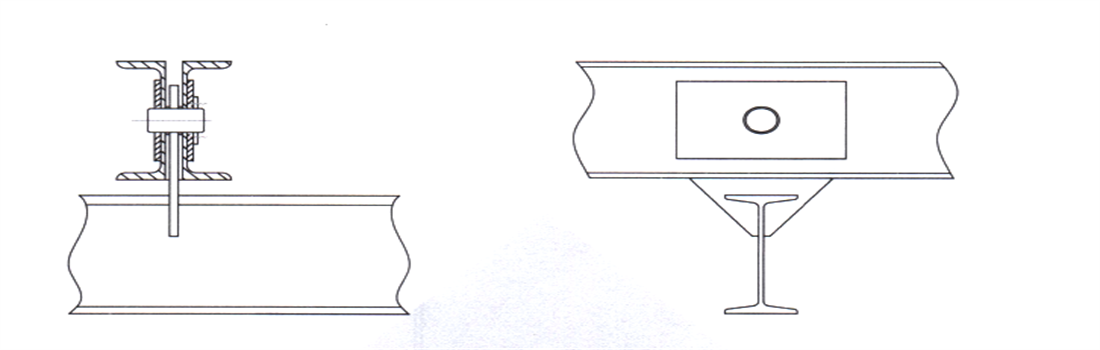
3)Pin type connection (Figure 2-10): The main girder and end girder of the suspension electric single girder overhead adopts a pin shaft connection to balance the wheel pressure of each wheel group, and improve the contact condition between wheels and rail.
Figure 2-10 Connection of Main and End Girders
2.5 Driving device
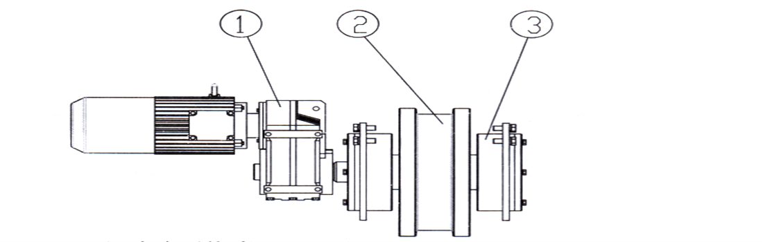
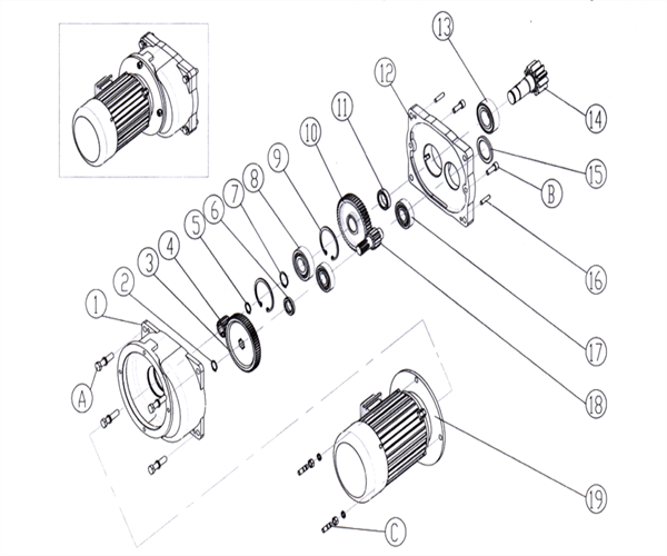
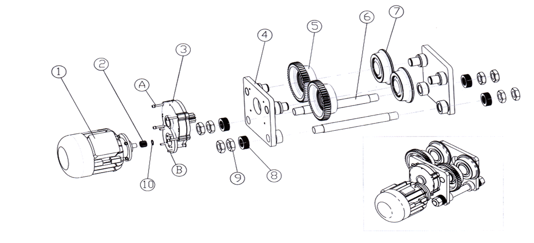
2.5.1 LD driving device
Soft start squirrel cage motor with built-in flat brake is used for ground operation; When operating in the driver's cab, a conical wound brake motor is used, and the brake is a conical brake; The reducers all adopt one open one closed or one open two closed in volute gear reducers, and the open gear is connected to the wheel through bolts as a whole.
Figure 2-11 LD - type Driving Device
1-box A 2-retaining ring 3-big gear wheel 4-pinion 5-retaining ring 6-spacer bush 7-retaining ring 8-bearing 9-retaining ring 10-big gear wheel
11-spacer bush 12-box B 13-bearing 14-gear shaft 15- stuffy cover 16-locating pin 17-bearing
18-gear shaft 19-brake motor A/B/C: fastening bolt
2.5.2 LX driving device
Suspension electric single girder overhead adopts an electric trolley as the driving device, consisting of brake motor, reducer, and wheel device. The motor is a conical rotor squirrel cage type, equipped with a flat brake, and the brake ring is integrated with the fan wheel. By using an open closed gear reducer, the wheels with a single toothed rim are driven to rotate. Both the active and passive wheels have a single rim structure.
Figure 2-12 LX - type Driving Device
1-travelling motor 2-pinion 3-reducer 4-wallboard 5-driving wheel 6-wire dowel 7-driven wheel
8-adjsuting washer 9-nut 10-retaining ring AB-fastening bolt
2.6 Wheel
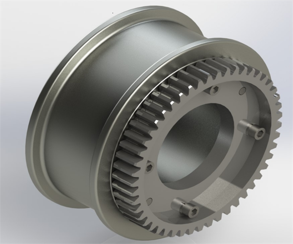
2.6.1 LD wheel
LD electric single girder overhead travelling wheels are forged with 45 # steel and have a double rim structure. The wheel tread is cylindrical, in line contact with the square steel track, and in point contact with the light rail or heavy rail. The side of the wheel is equipped with a gear ring, which is used in conjunction with the driving pinion to rotate the wheel.
Figure 2-13 LD-type Wheel Block
1-axle 2-retaining ring 3-dust cover 4-bearing 5-wheel 6-bush
2.6.2 LX wheel
The travelling of the electric hoist and suspension electric single girder overhead adopts a single wheel rim structure wheel, forged with 45 # steel, with a conical drum shaped surface on the wheel tread and point contact with the rail. The rim of the active wheel is machined with a tooth shape, which serves as an open gear for low speed output through a reducer.
Figure 2-14 LX- type Wheel Block
1-driving wheel 2-holed cover 3-bearing 4-retaining ring 5-stuffy cover 6-retaining ring
2.7 Technical data sheet
| Lifting Capacity(T) |
1-5 |
10 |
16 |
20 |
| Span(m) |
7.5-30 |
7.5-30 |
7.5-30 |
7.5-20 |
| Crane travel Mechanism |
travel speed(m/min) |
20 (Gound) |
30 (Cab) |
20 Ground) |
30 (Cab) |
20 Ground) |
20 Ground) |
| speed ratio |
58.78 |
39.38 |
58.78 |
39.38 |
58.78 |
58.78 |
| motor |
power(kw) |
2*0.8/4*0.8 |
2*1.5 |
2*1.5/4*0.8 |
2*1.5 |
2*1.5/4*1.5 |
4*1.5 |
| rotation speed(n/min) |
1380 |
7.5-22.5/22.5-31.5 |
7.5-22.5 |
7.5-14/14-19.5 |
7.5-31.5 |
| Electric Hoist |
Electric hoist |
single speed |
double speed |
single speed |
double speed |
single/double speed |
single/double speed |
| Lifting speed(m/min) |
8 |
8/0.8 |
7 |
7/0.7 |
3.5 |
3.5 |
| Cross speed(m/min) |
20 |
20 |
20 |
20 |
| Motor |
cone squirrel-cage model |
cone squirrel-cage model |
cone squirrel-cage model |
cone squirrel-cage model |
| working class |
A3 A4 A5 |
A3 A4 A5 |
A3 A4 A5 |
A3 A4 A5 |
| Power voltage |
380V-690V |
380V-690V |
380V-690V |
380V-690V |
| wheel diameter(mm) |
Φ270 |
Φ270 |
Φ270 |
Φ270 |
| Rail width |
37-70mm |
37-70mm |
51-70mm |
51-70mm |
3.Electrical control system
3.1 Overview
- ♦ Electric single girder overhead works intermittently and repeatedly to lift, lower, and run horizontally in three-dimensional space through hooks or other lifting devices. Its electrical equipment mainly consists of an electric control box, travel switch, handheld controller, and cables, with functions such as voltage loss, limit, and overload protection.
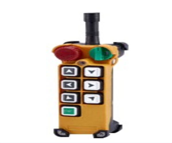
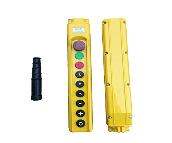
- ♦ The handheld controller is used to control crane’s lifting, lowering, trolley operation, it is divided into two types: suspended flashlight or remote control. The control voltage of the handheld controller or remote control is 36V. According to the direction symbol shown above, press the button correctly, and control the action of the electric single girder overhead through the opening and closing of the contactor in the electric control box.
- ♦ Electric single girder overhead can also be operated by an open or closed driver's cab, equipped with an operating platform and a cam or master controller inside. By grading the switching resistance through the action of the hand wheel or handle, the lifting, lowering, speed regulation, small car operation, and large car operation of the electric single girder overhead can be achieved.
- ♦ When two or more control methods are used, there is an interlocking function to ensure that at any given time, only one control method is effective and the other is used as a backup.
- ♦ The connection between electrical equipment adopts copper core multi-stranded wires.
- ♦ The electric control box is installed on the passive side of the electric trolley, and a large electric control box is installed at the end of the main girder. When operating in the driver's cab, a resistor is installed on the top of the cab, and the electrical cabinet is placed inside the cab.
3.2 Power source
3.2.1 Under normal working conditions, the voltage fluctuation of the power supply system at the connection point of the crane feeder shall not exceed 10% of the rated voltage.
3.2.2 The power supply is three-phase AC, with a rated frequency of 50Hz or 60Hz. The rated voltage is 220V~660V, and the upper and lower limits of allowable voltage fluctuations on motors and electrical control equipment are ± 10%. The internal voltage loss of electric single girder overhead is not more than 3%.
3.3 Impact on the environment and energy
When a mechanism with a larger capacity starts, it can cause instantaneous impact and voltage drop on the power grid with a smaller capacity, and even affect the normal operation and starting of equipment hung on the same power source.
3.4 Power feeding mode
3.4.1 The crane feeding device adopts the form of safety sliding wire, seamless sliding contact wire, or cable pulley.
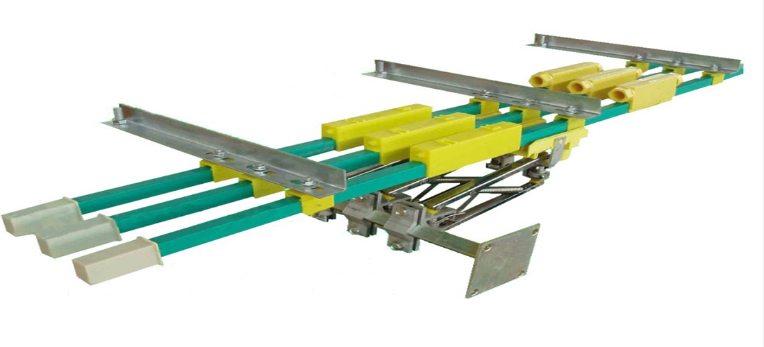
1) Safety sliding wire: The safety sliding wire is an energy-saving sliding contact wire developed based on advanced foreign experience and national conditions. It has safe, reliable, and excellent mechanical and electrical performance, making it easy to install and maintain. The protective shell is made of two materials: engineering plastic and aluminum plastic alloy, and the conductor is made of aluminum alloy (embedded with stainless steel bars) or pure copper. See Figure 3-1.
The sliding wire is composed of a sliding wire guide rail (fixed part, connected to the power supply, and the guide rail is connected by a single length of 4m/piece or 6m/piece) and a collector (sliding part). It can slide on the sliding track or inside and come into contact with copper bars for power supply, and is installed on electric single girder overhead girder through brackets and suspension clips.
2) Seamless sliding wire: The seamless sliding wire is a continuous type without joints, and uses oxygen free copper as the conductor to transport power. The copper and plastic are in close contact and will not have poor contact due to vibration; The insulator is PVC+impact resistant, without joints, with low voltage drop; The collector arm is long and equipped with independent tension springs, suitable for the power introduction of small and light cranes. See Figure 3-2.
3) Cable pulley: Refer to the feeding method of the small car (electric hoist). See Figures 3-3 and 3-4.
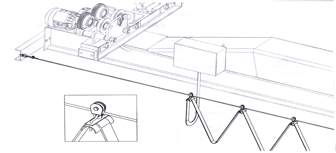
4) Soft cable: Using the tensioned steel wire rope as the support, the flexible cable is suspended on the tensioned steel wire through a suspension ring or pulley, and is dragged by the movement of the electric single girder overhead.
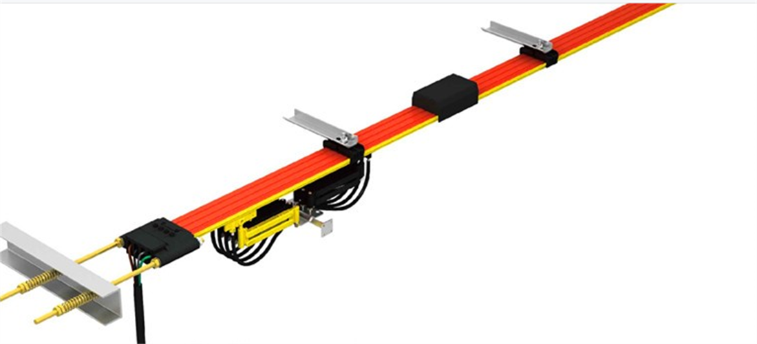
Figure 3-1 Safety Wire Power Feeding
Figure 3-2 Seamless Sliding Wire Power Feeding
3.4.2 The feeding device of the trolley (electric hoist) adopts a cable pulley type. The flexible flat cable is introduced through a suspended cable pulley, and the angle steel or steel wire rope arranged on the transmission side of the electric single girder overhead serves as a slide, which moves with the trolley (electric hoist).
Figure 3-3 Angle steel power feeding
Figure 3-4 Wire rope power feeding
3.5 Electrical control
Electric hoist electrical can control the starting, reversing, braking, and stopping of the lifting and travelling motors, completing their vertical lifting and horizontal horizontal movement. It is generally composed of power supply introduction devices, contactors, control flashlights, and limit switches connected through wires.
For safety reasons, there is a loss of voltage protection and a main power switch, and the lifting mechanism is equipped with a lifting bidirectional fire limit device and a heavy hammer type limit device.
3.5.1 Bridge travelling electrical control
When electric single girder overhead is operated by a ground handheld controller, the crane long travelling motor is single speed or dual speed squirrel cage motor; when operated by the driver's cab, the motor is mostly a wound wire motor or a single speed squirrel cage motor+frequency converter.
- 1) Single speed squirrel cage motor control: the starting, braking, and reversing of the motor rely on a handheld controller to control the contactor for indirect control. The control method is simple and the use of electrical components is minimal. No speed regulation performance. Frequency converters can be added as needed to improve braking performance, but they cannot operate at low speeds to avoid motor heating.
- 2) Dual speed squirrel cage motor control: The electric single girder overhead motor is a 2/8 level, 1/4 speed ratio dual winding dual speed squirrel cage motor, achieving different speeds and operating speeds by changing electrodes number. The starting, braking, and reverse rotation of the electric motor rely on a handheld controller to control the contactor for indirect control. Slow starting or braking can be used to reduce the impact vibration during starting and braking, and improve the starting and braking performance. Utilize rapid improvement in homework efficiency.
- 3 )Driver's cab control: Electric single girder overhead motor is wound type, combined with resistor, to increase the rotor resistance to limit excessive starting current, reduce the impact during starting, and ensure a large starting torque to adapt to the characteristics of lifting operations. By using a cam controller or master controller, the starting, speed regulation, and commutation of the wound motor can be controlled by rotating the hand wheel or shifting the handle to switch the resistance in a hierarchical manner.
-
3.6 Common Electrical Appliances
3.6.1 Controller
Control electrical appliances are electrical appliances used to connect or disconnect circuit connections. According to different operating methods, they are divided into ground operated control electrical appliances and cab operated control electrical appliances.
Ground operated control appliances include cable pendant and remote controls, while cab operated appliances include cam controllers or master controllers
3.6.1.1 Cam controller
The cam controller is used for controlling motor’s running during cab operation. Turning the hand wheel can change the resistance value of the stator circuit or rotor circuit of the winding motor in a predetermined order, achieving direct control of the motor's starting, speed regulation, commutation, braking, and stopping. This controller has a reversible symmetrical circuit and is suitable for motors with small capacity. A resistor is required to limit the starting current of the motor and reduce the impact of starting.
3.6.1.2 Master controller
The master controller, in conjunction with the contactor, can control the starting, speed regulation, reverse rotation, braking, and stopping of the motor. By moving the handle, the contacts can be opened and closed in a predetermined order, achieving the purpose of issuing commands or interlocking and switching with other control circuits.
3.6.1.3 Control box
The control box is used for electric hoist control and ground operation of cranes, which is equipped with components such as contactors, transformers, circuit breakers, and air switches.
It is divided into a hoist control box and a crane control box. The hoist control box is installed on the passive side of the electric hoist to control the lifting and operation of the electric hoist. Electric single girder overhead control box is installed at the end of the main beam of the crane to control the operation of the crane.
The main electrical component in the control box is an AC contactor, which can be used to connect and disconnect the main circuit, and can be remotely controlled and frequently operated.
3.6.1.4 Control cabinet
The control cabinet is used for driving and controlling the electric single girder overhead operated by the driver's cab. It is installed in the driver's cab and is equipped with components such as contactors, transformers, circuit breakers, overcurrent relays, indicator lights, and air switches. It can be used in conjunction with cam controllers, master controllers, or remote controls to control motor starting, speed regulation, commutation, braking, and stopping.
3.6.2 Protecting electrical appliances
Protecting electrical appliances are used to protect the safe operation of electrical equipment such as electric motors, including circuit breakers, over-current relays, main switches, lifting limiters, running limiters, and overload limiters.
3.6.2.1 Main switch
The main switch is the main electrical appliance that serves as the overall protection to electric single girder overhead, integrating control and multiple protection functions. In addition to completing contact and breaking circuits, it can also protect circuits or electrical equipment from short circuits, severe overloads, and under-voltages.
3.6.2.2 Limiter
1) The limiter is used to limit crane’s operation of various mechanisms within a certain safety range, avoiding collision hazards.
The lifting limit device of the electric hoist is a bidirectional lifting limit structure, which uses the lateral movement of the rope guide to push the limit rod to collide with the limit switch and achieve the up and down limit function.
2)The travelling limit switch adopts a mechanical limit switch, fixed at both ends of one end girder. When the safety ruler installed on the side of the factory touches the limit switch, the control circuit can be disconnected. The mechanism can only operate in the opposite direction.
3.7 Lighting and communication
3.7.1 Lighting
Indoor lighting adopts energy-saving fluorescent lamps.
3.7.2 Communication
▲ Electrical bell
▲ Sounder (optional)
▲ Audible and visual alarm (optional)
During the operation of the electric single girder overhead, the driver can use the above devices to remind ground or other relevant operators, playing a safety warning role.
3.8 Operating equipment
3.8.1 Cab
The driver's cab is arranged at the end of the bridge and is equipped with an operation console, which is equipped with operating handles and function buttons to control the starting, speed regulation, reversing, and braking of the electric motor, and to achieve the operation of lifting mechanisms, large vehicles, and small vehicles.
3.8.2 Cable pendant
The cable pendant is equipped with start, stop, action buttons, and emergency switches. The control voltage of the flashlight door is 36V. According to the direction symbol shown above, press the button correctly, and control the action of the electric single girder overhead by manipulating the contactor in the electric control box to open and close.
The operation button of cable pendant is equipped with mechanical and electrical interlocking protection to prevent two opposite actions from occurring simultaneously.
3.8.3 Remote controller
The wireless remote control is equipped with a transmitter and a receiver. The transmitter consists of an encoding circuit and a transmitting circuit, while the receiver consists of a receiving circuit and a decoding circuit.
The transmitter encodes the button signal, converts it into electromagnetic waves after modulation, and emits it. The receiver filters and amplifies the received electromagnetic wave signal, decodes and identifies it to control the relay, and drives electrical components and motors to achieve remote control of the electric single girder overhead.
The receiver is installed in a random control box, and the operator can freely move around with the transmitter and select the best safe visual position for operation.
3.8.4 Multi-point control
When using multi-point control methods such as cable pendant+remote control or cab+remote control, there is an interlock function to ensure that only one control method is effective at any given time. Each control point is equipped with an emergency switch.
3.9 Layout of electrical equipment
The electrical equipment of the electric single girder overhead is mainly arranged in the main girder, trolley (electric hoist), and driver's cab.
The bridge is equipped with a electric single girder overhead conductive frame at the end of the crane feed sliding line, which is used to install the sliding line collector.
The electric control box of the hoist is installed on the passive side of the electric trolley, and the electric control box of the crane is installed at the end of the main beam. The transmission side of the main beam is equipped with a hoist powered sliding back, which is introduced into the flat cable by a cable pulley.
Install the operating equipment and control cabinet of the electric single girder overhead in the driver's cab, such as the operating console, lifting capacity limiter display screen, etc.
Please refer to the electrical equipment layout diagram provided with the machine for specific layout.
3.10 Crane electric drawing identification
In the electrical drawing of cranes, codes are used to represent the electrical equipment of each mechanism. The commonly used codes are shown in Table 3-1.
| Code |
Name |
Code |
Name |
| KO |
Main contactor |
1Ds |
Rapid lifting and lowering motor |
| KM1/KM2 |
Long travelling contactor |
2Ds |
Slow lifting and lowering motor |
| KM3/KM4 |
Hoist travelling contactor |
DX |
Hoist travelling motor |
| KM5/KM6 |
Hoist rapid lifting and lowering contactor |
1Dd/2Dd |
Long travelling motor |
| KM7/KM8 |
Hoist slow lifting and lowering contactor |
S90 |
Lifting and lowering limiter |
| T |
Transformer |
S91/S92 |
Travel limit switch |
| Q0 |
Main circuit breaker |
s1-7/8 |
Lifting and lowering button |
| Q01 |
Micro circuit breaker |
s1-5/6 |
Hoist travelling button |
| E60 |
Plane current collector |
S1-3/4 |
Crane travelling button |
| -S40d |
Cam controller |
S1-2 |
Stop button |
| JT |
Emergency stop button |
S1-1 |
Starting button |
| Rd |
Resistor |
F21 F22 |
Overcurrent relay |
| H20 |
Electric bell |
H01 H02 |
Single light |
3.11 Variable frequency speed control
Please refer to the accompanying product manual and drawings for details.


.png)