Kingda ladle crane (or casting crane) is the special hoisting equipment used in metal smelting environment, can carry out transshipment. Casting, hot molten metal charging and other operations of molten metal by intermittent and repetitive modes during smelting process. Ladle crane (or casting crane) has lifting & lowering and long travel & cross travel functions. Spreader device is hook or gantry-type laminated plate hook, the work class is A7-A8.
According to different structure, kingda ladle crane (or casting crane) can be divided into the following types:
Table1-1 Crane Type
Model
Name
Characteristics
YZ
Double girder ladle crane (casting crane)
It adopts double-girder, double-rail or four-rail, single(double)-trolley structure. The trolley is configured with hoisting mechanism and can finish molten metal lifting-transporting, tip ladle, etc. The spreader device of main hoisting mechanism is gantry-type laminated plate hook and the spreader device of auxiliary hoisting mechanism is forging hook used to assist the main hook to flip ladle or lift general goods.
YZS
Four girder ladle crane (casting crane)
It adopts four-girder-four rail or six-rail & double-trolley structure. The spreader device of main trolley is gantry-type laminated plate hook and the auxiliary trolley is forging hook. They work on separate rails, can realize the conveying &tipping of molten metal, lifting general goods, etc.
Note: above are only existing models, excluding the new products in application.
1.2 Model representation method
YZ
300/50t
—
19m
A7
working class
span
rated lifting capacity
crane mode
1.3 Main applicable laws, regulations and standards for the design and manufacturing
Decree No. 549 of the State Council
Regulations on Safety Supervision for Special Equipment
TSGQ7016
Lifting Appliances Installation, Modernization & General Overhaul Supervision inspections Regulation
GB/T 3811
Design Rules for Cranes
GB 6067.1
Safety Rules for Lifting Appliances
GB 6067.5
Safety Rules for Lifting Appliances一Party 5: Bridge and Gantry Cranes
GB/T 5905
Cranes-Test Code and Procedures
JB/T7688.1
Specifications for Metallurgy Cranes一General Requirements
JB/T7688.15
Specifications for Metallurgy Cranes一General Requirements
GB/T 20303.1
Cranes-Cabins-Part 1:General
JB/T 8437
Wireless Remote-Control Unit of Hoisting Machinery
GB 12602
Lifting Appliances-Safety Devices against Overload
GB 8918
Steel Wire Ropes for important Purposes
GB/T10051.1-10051.15
Lifting Hook
JB/T 4315
Crane Electric Control Equipment
1.4 Environmental conditions
1.4.1 Kingda ladle crane (casting crane) operating environment temperature and humidity shall satisfy the following requirements
1. Operating environmental temperature is generally -10C~+60℃ 2. Relative humidity under +40℃ shall not exceed 50%
2. Relative humidity under +40℃ shall not exceed 50%
1.4.2 There shall not be any inflammable, explosive or corrosive gas in working environment
1.4.3 The altitude of Kingda ladle crane (casting crane) installation and working shall not exceed 1,000m (when it exceeds 1,000m, it’ s required to check the motor capacity: when it exceeds 2,000m, it’ s required to check the capacity of electrical devices).
Note: when it exceeds above said range, shall be solved by the user and manufacturer through negotiation.
1.5 Working conditions
1.5.1 The power supply should be three-phase AC (three-phase four-wire system) and the rated frequency shall be 50Hzor 60Hz. The rated voltage shall be 380V (it can also be 415V, 660V, 1KV, 3KV, 6kV or 10kV according to end user’s demands). And voltage fluctuation of power system feeding line’s connection shall not exceed + 10% of the rated voltage.
1.5.2 Ladle crane (casting crane) shall be mounted on the special rail beam, and run along the rail to hoist the object. The rail shall be laid according to GB/T 10183.1 Cranes-Tolerances for Wheels and Travel and Traversing Tracks-Part 1: General and satisfy the following requirements:
1) Rail span difference:3-10mm
2) Rai top surface elevation difference: 10min
3) Height difference in the same rail cross section: <10mm
4) Rail gradient: ≤ 1/1000mm
5) Joint gap:1-2mm
1.5.3 Both ends of the rail beam shall be configured with stop buffer to prevent the crane from rushing out of the rail
1.5.4 Minimum safety distance between the crane and building shall comply with the following requirements: Upper clearance ≥200mm,lateral clearance ≥100mm 1.5.5 Ground resistance value of the crane’s running rail shall not be larger than 4M (in the charge of the user).
1.6 Environmental impacts
During the installation, use and maintenance process, in case it’s not handled properly, it may result in impacts on surrounding environment. Specific impacts are as shown in the following table:
Table 1-4 Environmental Impacts
Item
Environmental impacts
Avoidance measures
Installation, maintenance or disassembly
A certain quantity of solid wastes will certainly be generated during the construction process
Dispose the solid wastes according to local regulations
Leakage lubricating oil
It will result in soil and water pollution
Check the leakage part and satisfy leakage-free requirement
Replacement of lubricating oil
Arbitrary dumping will result in soil and water pollution
tore the waste oils and greases in a special vessel
Engagement part is seriously worn
The noise exceeds the standard, which will influence the equipment operator
Calibrate, adjust or replace the wear-out parts
2. Ladle Crane Structure characteristics
2.1 Overview
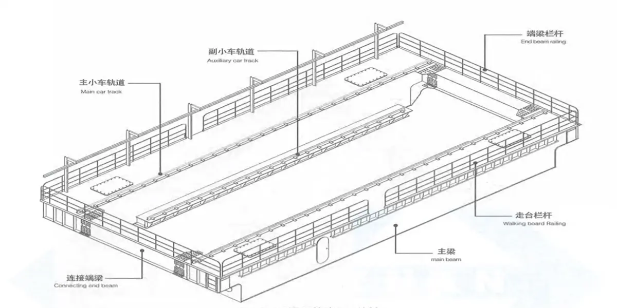
The kingda ladle crane (casting crane) mainly consists by bridge frame, hoisting trolley, crane travelling mechanism, accessories and electrical control system.
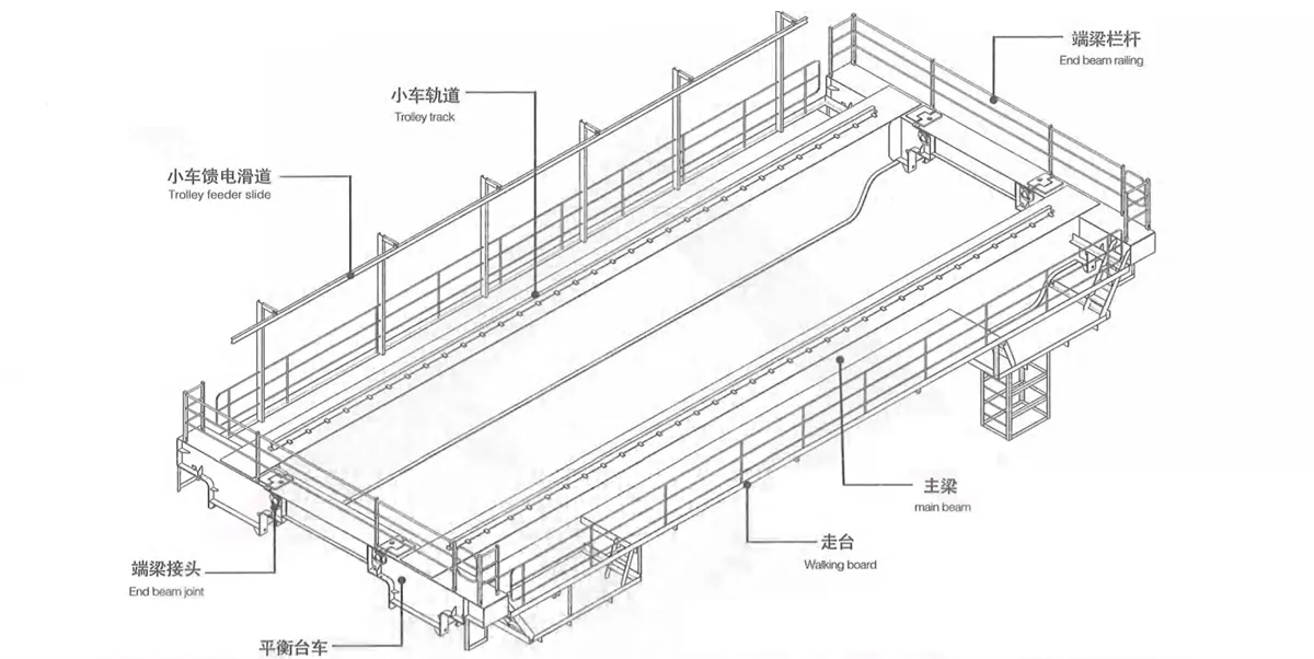
The main beam, as the main structural member bearing the weight, is divided into two forms-narrow beam and wide beam, and is configured with rail, which is in right-rail or off-rail arrangement for cross travel of the hoisting trolley along main girder direction. The end girder is configured with joint, bolt or pin connection, for easy to disassembly and transport bridge frame.
A walking board is set outside the narrow beam for placing crane long travelling mechanism and electric devices, and is also configured with protection railing. Crane long travelling mechanism and electric devices can be arranged inside the wide beam.
1) Hoisting trolley is configured with transmission mechanism, steel rope winding system and safety device. Trolley fame as the carrier, it can carry out cross movement along the rail which is laid on the main girder.
2) The cross travelling mechanism adopts respective transmission or centralized transmission.
3) Crane can be operated through cab or remote control, etc.
4) Hoist trolley feeding mode employs 工steel sliding way or cable trolley introducing flat cable.
5) Crane power feeding mode includes angle JGHX or angle steel sliding wire, etc.
According to different structures, the ladle crane (casting crane) can be divided into the following 4 structural styles:
1) Double-girder, double-rail & single-trolley, it’s used for medium and small tonnage rated lifting capacity ladle crane. Main and auxiliary hoisting mechanisms are set on the same trolley, the distance between main hook and auxiliary hook is fixed, and the main hook is gantry-type aminated plate hook or forged hook hanging gantry-type laminated plate hook. It can convey the ladle filled with molten metal or other goods. Auxiliary hook is forged hook or plate hook, used to assist the main hook with dumping, tipping and conveying of other goods.
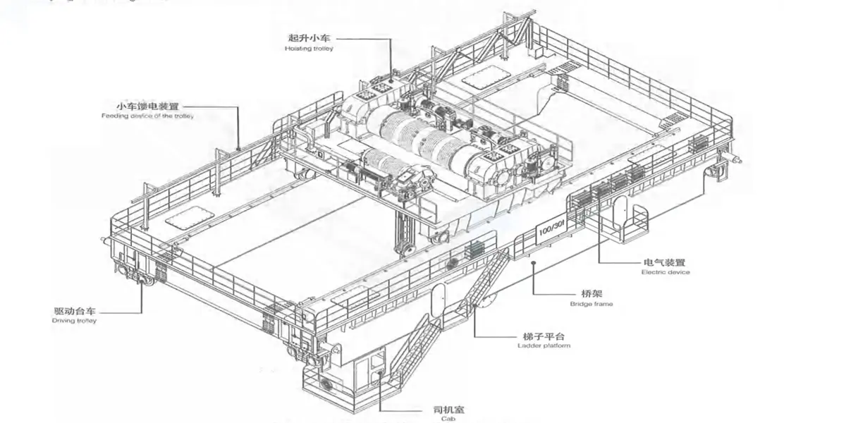
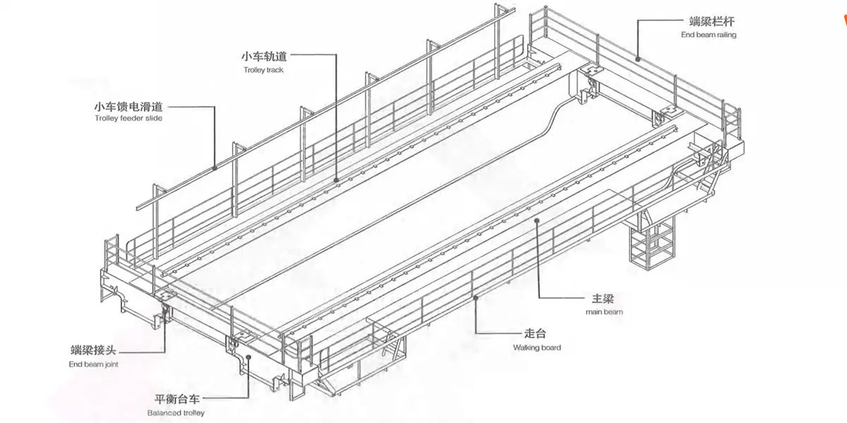
2) Double-girder, four-rail & double-trolley type: it is used for the medium and small tonnage rated lifting capacity casting crane. Main trolley and auxiliary trolley share two main girders, The main trolley runs on the rail above the main girder. While auxiliary trolley runs on the rail under inner side of he main girder, but it can’t pass under the main trolley. Main hook is gantry-type laminated plate hook and used to convey the ladle with molten metal. While auxiliary hook is forged hook or plate hook and used to assist the main hook with dumping, tipping and conveying of other goods.
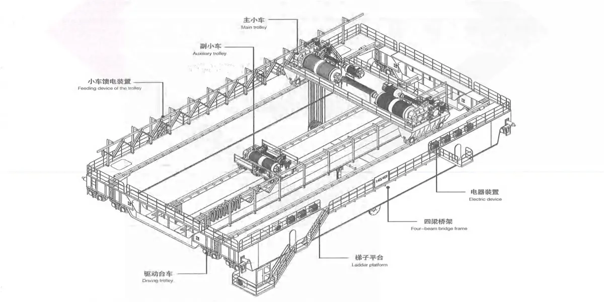
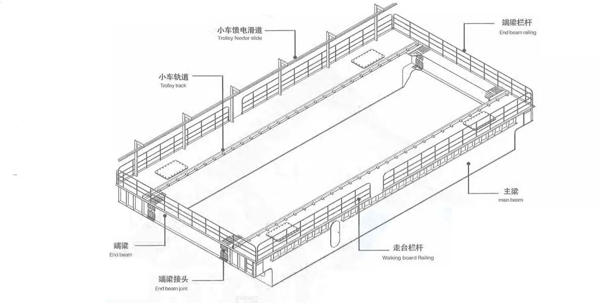
3) Four-beam, four-rail & double-trolley type: it is used for the medium and large tonnage rated lifting capacity crane. Main trolley runs on two main girders and auxiliary trolley runs on two auxiliary main girders, auxiliary trolley can pass under the main trolley running on two auxiliary main girders Main hook is gantry-type laminated plate hook and used to convey the vessel with molten metal, while auxiliary hook is forged hook or plate hook used to assist the main hook with dumping, tipping and conveying of other goods.
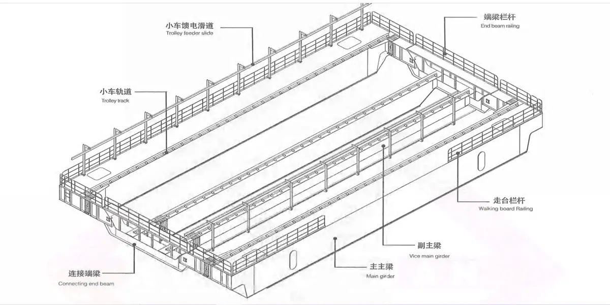
4) Four-girder. six-rail & double-trolley type: it is used for the crane with super large tonnage lifting capacity ladle crane, The main trolley consists of one upper trolley and two lower trolleys, which are integrated into an organic whole by four spherical hinges. The girder frame is four-girder & six-rail form and consists of two outside main bears, two inside main girder, two end girder and accessories. Two lower trolleys of the main trolley run on the track set above internal web plate of outside main beam and external web plate of inside main beam, while auxiliary trolley runs on the track set above internal web plate of inside main girder and can pass under the main trolley. Main hook is gantry-type laminated plate hook and used to convey the ladle with molten metal, while auxiliary hook is forged hook or plate hook and used to assist the main hook with dumping, tipping and conveying of other goods.
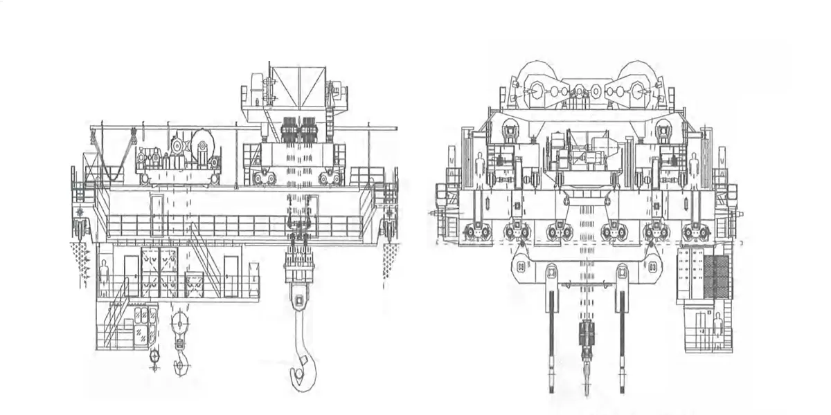
Figure 2-1 Profile of Double-beam, Double-track & Single-trolley Crane
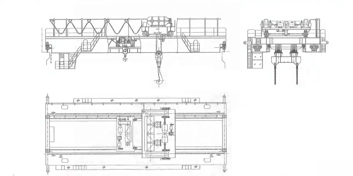
Figure 2-2 Profile of Double-beam, Four-track & Double-trolley Crane
Figure 2-3 Profile of Four-beam, Four-track & Double-trolley Crane
Figure 2-4 Profile of Four-beam, Six-track & Double-trolley Crane
2.2 Hoisting trolley
2.2.1 Overview
Kingda ladle crane (or casting crane) hoisting trolley is configured with hoisting mechanism, steel rope winding system, cross travelling mechanism and safety device. With trolley frame as the carrier. it can carry out horizontal movement along the rail laid on main girder.
Figure 2-5 Hoisting Trolley
2.2.1 Hoisting mechanism
Kingda ladle crane (or casting crane) hoisting mechanism is used to lift and lower objects vertically and consists of transmission device (motor, reducer, brake. Etc.), winding system (reel group, steel rope, pulley block, hook group, etc.), limit switch, overload limiter (electronic scale) and other safety protection devices. The motor’s power will be delivered to the reducer through coupling, gear box low-speed shaft will drive the reel to rotate to enwind steel rope, and it will realize the sling lifting and lowering functions by controlling forward and reverse rotations of the motor. To guarantee the safety in casting’s regular work and accurate locating, NC (normally closed) brake has been arranged reducer’s on high-speed shaft, the brake shoe will be opened during power-on and closed during power-off.
1)Main hoisting mechanism.
Ladle crane (or casting crane) main hoisting mechanism can be arranged in different forms according to different functions.
a. Double motors, double reducers and single drum: during the work, two motors drive two reducers simultaneously to drive the drum group to rotate. The winding of drum rope adopts two pulley blocks to form double lifting points. The spreader is gantry-type laminated plate hook. When a motor breaks down, it’ s able to drive the whole hoisting mechanism by the other motor to guarantee that the crane can complete a working cycle safely under the rated lifting weight. This form is mostly used by the medium and small tonnage rated lifting capacity ladle crane;
Figure 2-6 Hoisting Mechanism with Double Motors, Double Reducers and Single Reel
1-hoisting limit switch 2-reducer 3-transmission shaft 4-coupling 5-fixed pulley block 6-reel 7-motor 8-brake wheel coupling 9-brake
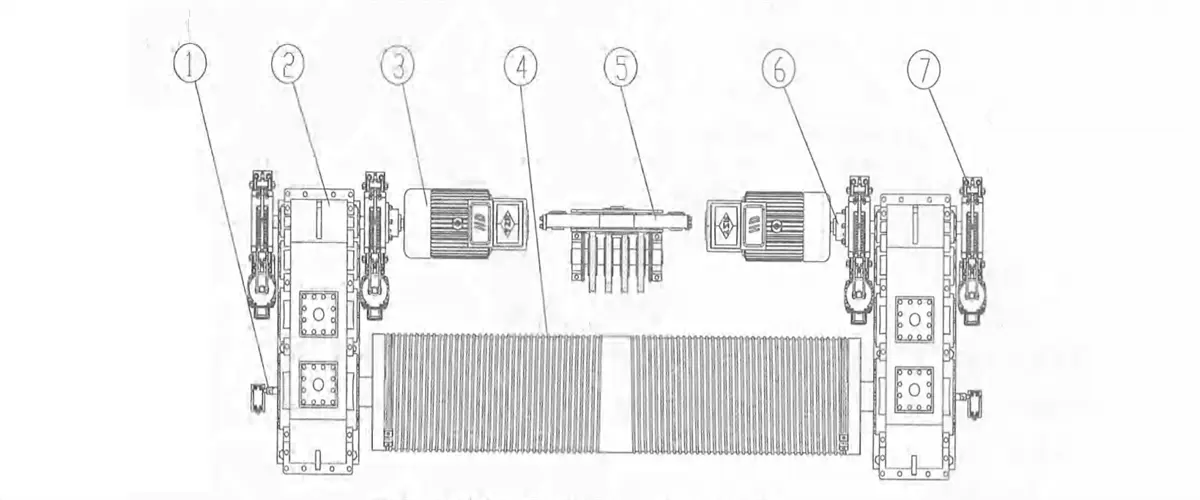
b. Double motors, double reducers and single drum: During the work, two motors drive two reducers simultaneously to drive the drum group to rotate. The winding of wire rope adopts a fixed pulleys block to form a single lifting point; The spreader is forged hook with gantry-type laminated plate hook suspending on it. When a motor breaks down, it is able to drive the whole hoisting mechanism by the other motor to guarantee that the crane can complete a working cycle safely under the rated lifting weight. This form is most used by medium and small tonnage rated lifting capacity ladle crane;
Figure 2-7 Hoisting Mechanism with Double Motors, Double Reducers and Single Ree
1-hoisting limit switch 2-reducer 3-mofor 4-reel 5-fixed pulley block 6-brake wheel coupling 7-brake
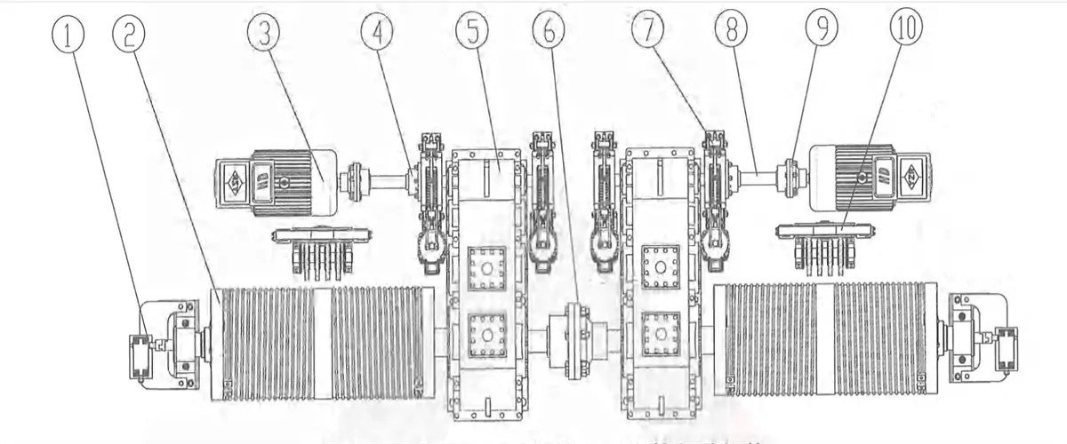
c. Double motors, double reducers and double drums: During the work, two motors drive two reducers simultaneously to drive the drum group to rotate. The winding of drum wire rope adopts two pulley blocks to form double lifting points. The spreader is gantry-type laminated plate hook. The reducer low-speed end will realize rigid connection of two reel groups through the coupling, so as to realize the purpose of synchronization. When a motor breaks down, it’ s able to drive the whole hoisting mechanism by the other motor to guarantee that the crane can complete a working cycle safely under the rated lifting weight. This form is mostly used by medium and small tonnage rated lifting capacity ladle crane;
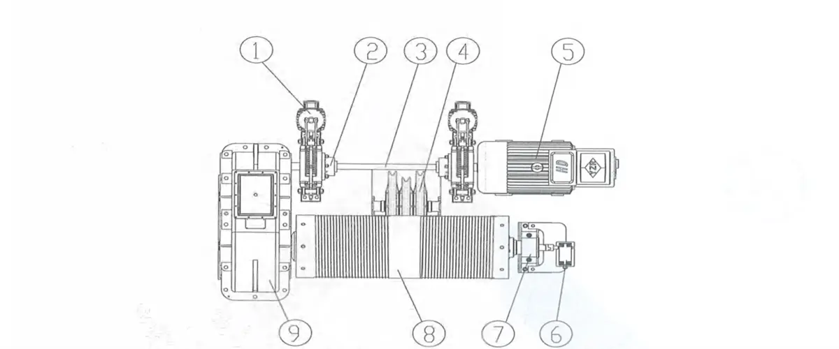
d. Double motors, single reducer and double drum: During the work, two motors drive a reducer simultaneously to drive two drums’ groups to rotate. The winding of steel wire rope adopts two pulley blocks to form double lifting points. The spreader is gantry-type laminated plate hook. The two drum groups are perpendicular to the main beam and the two mechanisms are interlocked through reducer’s low-speed shaft, to realize the purpose of synchronization. Working brake and supporting brake are configured on high-speed shaft. Safety brake is set at the end of the drum for emergency brake in emergencies. When a motor breaks down, it’s able to drive the whole hoisting mechanism by the other motor to guarantee that the crane can complete a working cycle safely under the rated lifting weight This form is mostly used by the medium and small tonnage rated lifting capacity ladle crane;
Figure 2-9 Hoisting Mechanism with Double Motors, Single Reducer and Double Reels
1-motor 2-transmission shaft 3-brake wheel coupling 4-reducer 5-fixed pulley block 6-brake 7-hoisting limit switch 8-safety brake 9-reel
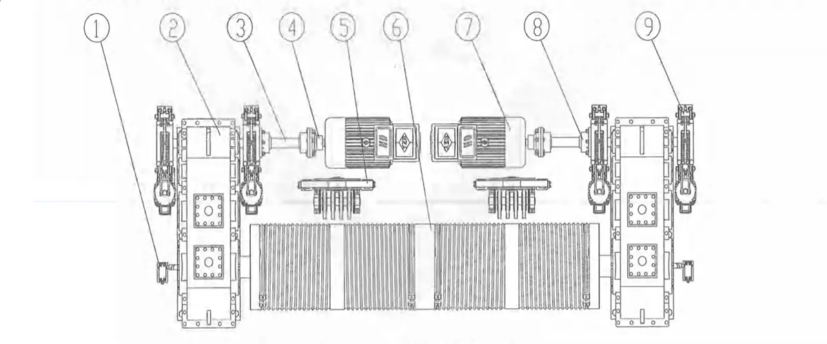
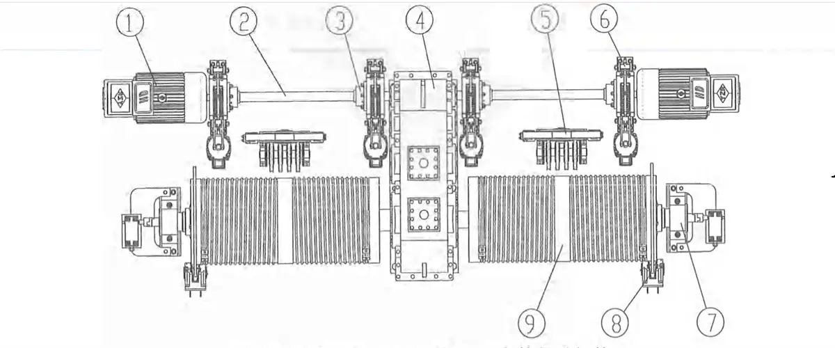
e. Double motors, three reducers and double drum: Three reducers are arranged in tripod shape and two drum groups are parallel to the main beam. During the work, two motors drive a high-speed reducer simultaneously and drive two secondary reducers through the coupling so as to drive two drum groups to rotate. It’ s able to set ratchet & pawl device inside the high-speed reducer as required. The winding of steel rope adopts two groups of pulleys to form double lifting points. The spreader is gantry-type laminated plate hook. Working brake and supporting brake are configured on high-speed shaft. Safety brake is set at the end of the drum for emergency brake in emergencies. When a motor breaks down, it’s able to drive the whole hoisting mechanism by the other motor to guarantee that the crane can complete a working cycle safely under the rated lifting weight. This form is mostly used by large tonnage rated lifting capacity crane;
Figure 2-10 Hoisting Mechanism with Double Motors, Three Reducers and Double Reels
1-safety brake 2-transmission shaft 3-brake 4-motor 5-brake wheel coupling 6-hoisting limit switch 7-reel 8-fixed pulley block 9-coupling 10-reducer
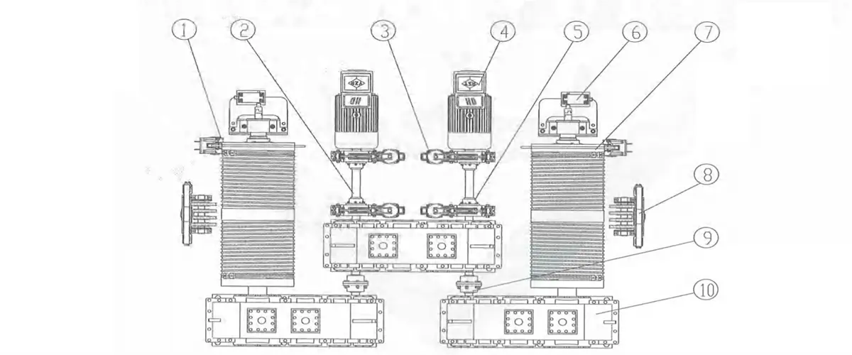
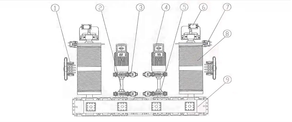
f. Independent large reducer: During the work, two motors drive a large reducer simultaneously to drive two drums to rotate. The winding steel wire rope adopts two pulley blocks to form double lifting points. The spreader is gantry-type laminated plate hook. The two drum are perpendicular to the main beam and the two mechanisms are interlocked through high-speed synchronizer gear in large reducer, so as to realize the purpose of synchronization. When a motor breaks down, it’ s able to drive the whole hoisting mechanism by the other motor to guarantee that the crane can complete a working cycle safely under the rated lifting weight. This form is mostly used by the crane with large tonnage.
Kingda ladle crane (or casting crane) auxiliary hoisting mechanism adopts single motor, single reducer and single drum arrangement. The winding of steel rope adopts a fixed pulley block to form single lifting points. The spreader device is forged hook. The overall arrangement is similar to general purpose overhead crane.
Kingda ladle crane (or casting crane) trolley travelling mechanism consists of motor, reducer, brake, transmission shaft, coupling, wheel group, etc., and can drive the trolley to move horizontally. The travelling mechanism has 4 arrangement forms:
1) Centralized transmission: one motor fixed on trolley frame driving the vertical reducer to drive the wheels on both sides to rotate through two transmission shafts. it’s applicable to four-wheel medium and small tonnage rated lifting ladle crane’s trolley.
2) Respective transmission: two motors fixed on trolley frame will drive two vertical reducers respectively to drive the wheels on both sides to rotate through the coupling. It is applicable to four-wheel trolley.
3) Respective transmission: two motors fixed on trolley frame, driving two vertical reducers respectively to drive the wheels on both sides to rotate. The reducer is mounted next to wheel side. One side will drive the wheel through coupling and one side will drive the wheel through universal coupling. t’s applicable to eight-wheel trolley with four girders and six rails.
4) Three-in-one respective transmission: employ 2 three-in-one reducing motors to drive the wheels on both sides to rotate directly.
Figure 2-16 Three-in-one Respective Transmission 1-Wheel Block 2-three-in-one reducing motor
2.3 Crane long travelling mechanism
Kingda ladle crane(casting crane)long travelling mechanism consists of motor, reducer, brake, transmission shaft, coupling, wheel block, buffer, etc. and can drive the crane to move longitudinally along the rail. The long travelling mechanism has 2 transmission forms:
1) Respective transmission: two or four motors will deliver the power to the reducer through coupling and transmission shaft respectively, and low-speed shaft of the reducer will drive the wheels on both sides to rotate through coupling.
2) Respective transmission: 2 or 4 motors will drive the reducer respectively, so as to drive the wheels on both sides to rotate through universal coupling (or transmission shaft). The motor and reducer will be connected through coupling. while the reducer and wheel block shall be connected by universal coupling (or transmission shaft).
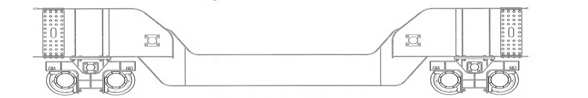
2.4.1 Kingda ladle crane (or casting crane) bridge frame is box-type double-beam or four-beam structure and consists of main beam, end beam, railing, walking board and accessories.
2.4.2 It is divided into three types according to different lifting capacity:
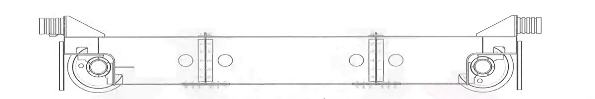
1) Double beam double rail - four wheels - narrow beam type bridge frame: middle rail or semi-off-rail or off-rail of trolley rail is arranged on the main beam (Figure 2-15a, b & c). Walking board is set on both sides of the main beam and consists of section steel and checkered plate. The walking board on transmission side is used to place crane long travelling mechanism and electric devices, the walking board on the driven side is used to place power feeding device-cable trolley. For convenient transportation, the main beam and end beam are welded as a whole, a joint is arranged in the middle of end beam to realize bolt connection for disassembling the bridge frame in two parts. This type casting crane is applicable small tonnage rated lifting capacity.
Figure 2-19 double beam double track four wheeled narrow beam type bridge frame
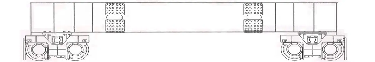
2) Double beam- Double rail- Eight wheels- narrow beam type bridge frame: middle trolley rail or semi-off-rail or of-trolley rail is arranged on the main beam (Figure 2-16a, b & c). Walking board is set on both sides of the main beam and consists of section steel and checkered plate. The walking board on transmission side is used to place crane long travelling mechanism and electric devices, while the walking board on the driven side is used to place power feeding cables trolley. The main beam and balancing bogies are welded into the whole, there is a connecting end beam between the bogies to realize bolt connection for disassembling the bridge frame into two parts for convenient transportation. This ladle crane is applicable to medium and small tonnage rated lifting capacity.
3) Double beam-double rail-wide beam type bridge frame: the main beam is wide-flange box-type structure. The upper part can be used as the channel of walking board. Off-track of trolley rail is arranged (Figure 2-16d) on the main beam, crane long travelling mechanism and electric devices are arranged inside the main beam, and there is an access door for personnel access. The main beam and box-type end beam employ bolt or pin connection for disassembling the bridge frame into two parts for transportation convenient. This ladle crane form is applicable to the large tonnage rate lifting capacity.
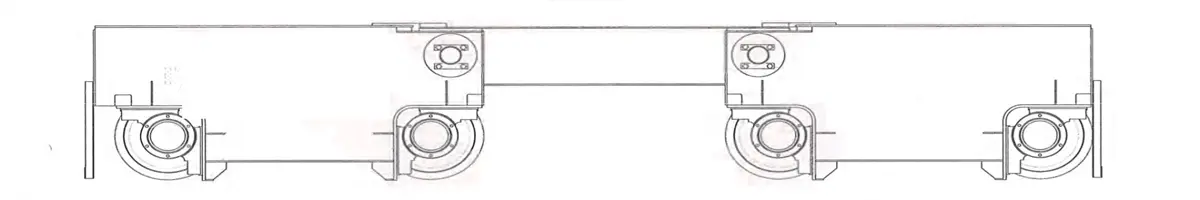
4) Four-beam & four-track wide beam type bridge frame: it consists of two main beams, two auxiliary main beams, two end beams and accessories. The main beam is wide flange box-type structure. Upper part can be used as the passage of walking board. The trolley rail is arranged on the main beam in off-track form (Figure 2-24d), crane operating mechanism and electric devices are arranged inside the main beam and access door is set for the access of relevant personnel. Auxiliary main beam is rich-track or off-track box-type narrow beam structure. One side is configured with walking board which is used to place cable trolley feeding device. The main beam and box-type end beam adopt bolt or pin connection, which is convenient for disassembling the bridge frame into two parts for transportation. This ladle crane is applicable to the medium and large tonnage rated lifting capacity.
Figure 2-22 Four-beam & Four-track Wide Beam Type Bridge Frame
5)Double-beam-four-rail wide beam type bridge frame: the main beam is wide flange box-type structure. Main and auxiliary trolleys share two main beams. The rail of main trolley is arranged on the main beam in off-track form, while the track of auxiliary trolley is arranged under inner side of the main beam (Figure 2-24e). Crane long travelling mechanism and electric devices are arranged inside the main beam, access door is set for the access of relevant personnel. The main beam and box-type end beam adopt bot or pin connection, which is convenient for disassembling the bridge frame into two parts for transportation. This ladle crane is applicable to medium and small tonnage rated lifting capacity.
Figure 2-23 Double-beam & Four-track Wide Beam Type Bridge
Figure 2-24 Main Beam Form
2.4.3 According to different structures, kingda ladle crane (or casting crane) end beam’s joint type falls into rigid type and flexible type.
1) Rigid angle steel type joint: the end beam‘s upper cover plate and web plate adopt angle steel type bolt connection. The lower cover plate adopts plate-type bolt connection. It is applicable to the ladle crane with medium and small tonnage rated lifting capacity. Please refer to Figure 2-25:
2) Rigid plate-type joint: the joint area adopts plate-type bolt connection. It is applicable to the ladle crane with large tonnage rated lifting crane. Please refer to Figure 2-26;
3) Flexible pin-type joint: the joint area adopts pin connection, lt is applicable to the ladle crane with large tonnage. Please refer to Figure 2-27 and Figure 2-28.
Figure 2-25 Rigid Angle steel Type Joint
Figure 2-26 Rigid Plate-type Joint
Figure 2-27 Flexible Pin-type Joint
Figure 2-28 Flexible Pin-type Joint
2.5 Main parts and components
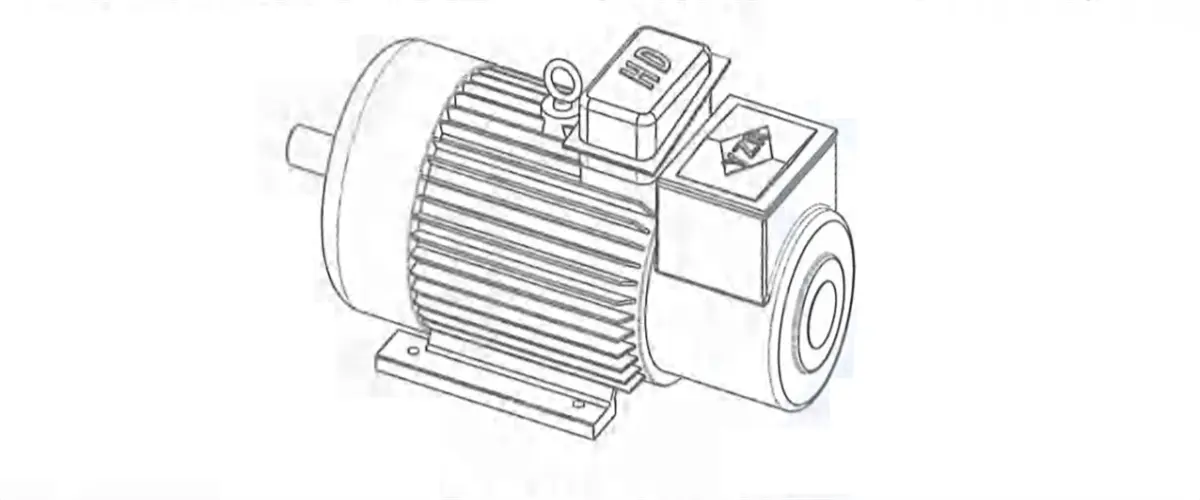
2.5.1 Motor
Kingda ladle crane (or casting crane) motor is YZR type three-phase asynchronous motor used for lifting and metallurgy industry, insulation grade: H, protection grade: IP54-65. It is applicable to short-term or intermittent period work. Lt is also able to employ frequency converter motor according to actual demand, which can cooperate with the frequency converter to realize 1:10 speed control. Rated parameter values of the motor are confirmed on the basis that working environmental temperature is not higher than 40'C and the altitude doesn't exceed 1 000m. In case any environmental factor changes, it will influence motor characteristics, please consult the manufacturer for specific working condition.
Figure 2-29 Motor
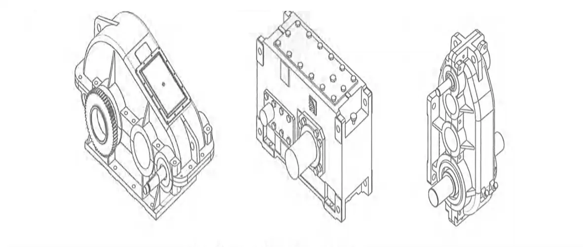
2.5.2 Reducer
Kingda ladle crane (or casting crane) reducer is a closed cylindrical gear transmission structure and an important transmission component for casting crane. It mainly plays the role of reducing high speed of the motor to working speed required by each mechanism. It can be mounted horizontally, vertically and by three pivot points. Horizontal installation is mainly used for hoisting mechanism and crane long travelling mechanism, while vertical installation is mainly used for trolley cross travelling mechanism. It can be divided into soft gear surface, medium-hard gear surface or hard gear surface according to the hardness of gear surface. The housing employs casting or welding structure and low-speed out shaft employs C-type gear plate or cylinder axis form
Figure 2-30 Reducer
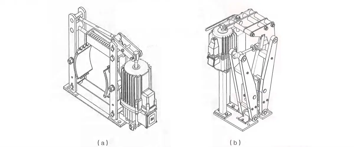
2.5.3 Brake
Kingda ladle crane (or casting crane) NC electric hydraulic brake will be opened during power-on and closed during power-of. t’s mounted on high-speed
shaft of the working mechanism to reduce braking torque.it can be attached with gasket abrasion automatic compensation, manual release, opening & closing limit and other special functions. lt can be divided into two structures according to structural form, namely, branch wheel type (Figure 2-31a) and plate type (Figure 2-31b).
Figure 2-31 Brake
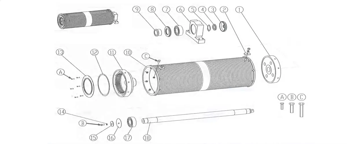
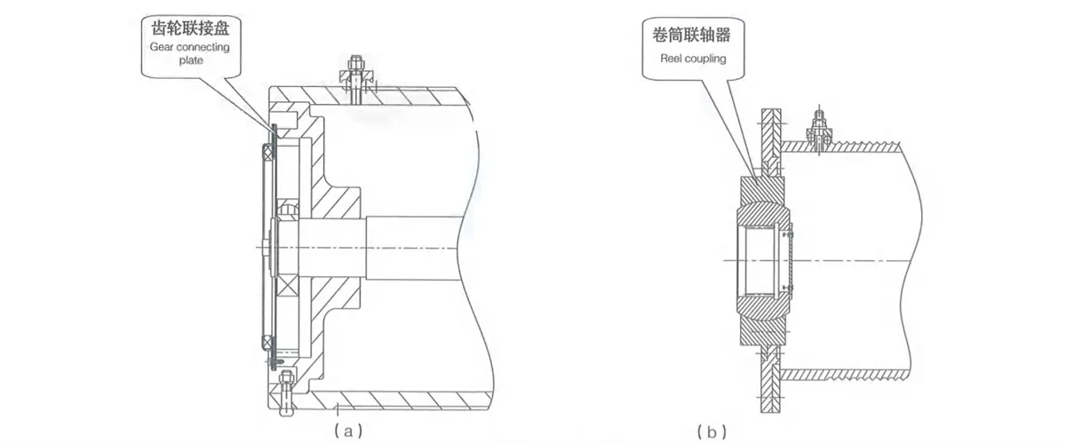
2.5.4 Drum
Kingda ladle crane (or casting crane) drum is the component in hoisting mechanism for winding steel rope, is made by steel plate through coiling, and employs long-axis or short-axis type tube structure. It adopts tooth-form connecting plate (Figure 2-33a) or reel coupling (Figure2-33b), etc. to connect with reducer coupling end. The other end is configured with bearing pedestal for fixing and supporting and overload limiter, rotary limit switch and other accessories can be mounted on shaft end.
The drum surface is machined with spiral rope groove, steel rope will wind it in a single layer, and pressing plate for fixing steel rope is mounted.
Kingda ladle crane (or casting crane) pulley block is used to guide the direction of steel rope and balance the branch tension of steel rope. lt can be divided into cast steel pulley or steel plate rolled pulley according to different materials. The main hoisting pulley block adopts balance arm structure.
Figure 2-34 Pulley Block of Aux. Pulley Block
1-fastening bolt 2-crane body 3-base plate 4-shaft end baffle 5-washer 6-nut 7-shaft 8-pulley 9-spacer bush 10-washer 11-round nut
Figure 2-35 Pulley Block of Main Hoisting Pulley Block
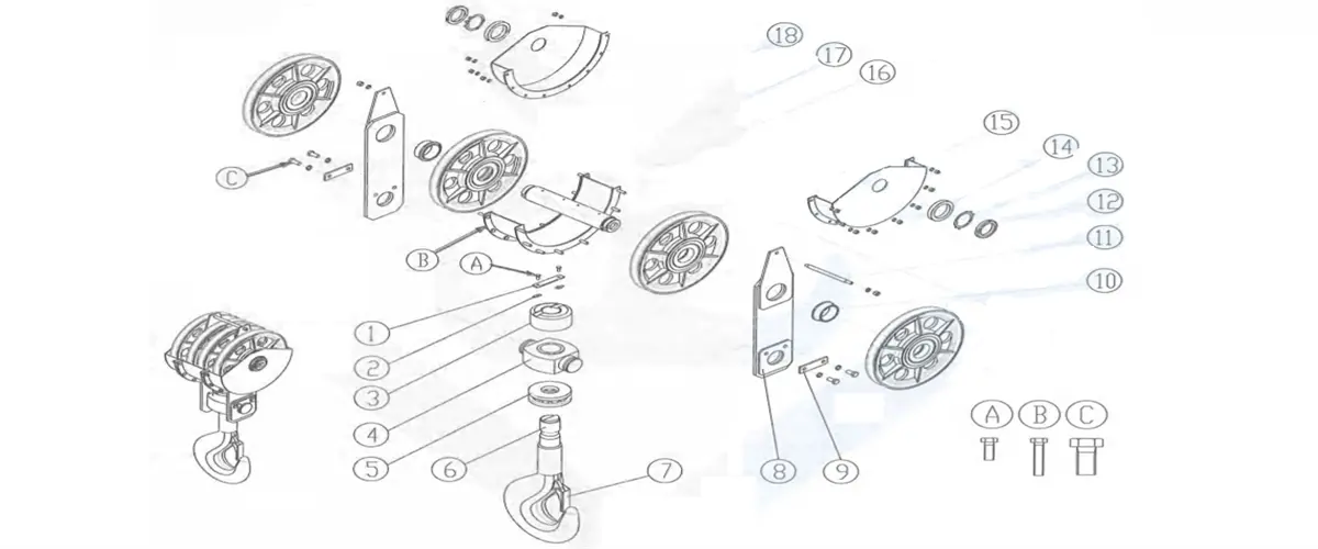
2.5.6 Spreader
2.5.6.1 Hook block.
Kingda ladle crane (or casting crane) hook block is the picking up device used most commonly on the crane, and consists of the hook with straight shank, hook nut, thrust bearing, hook cross beam, pulley, pulley shaft, pulling plate, etc. Shank part of the hook is machined with screw thread for mounting the nut to fix the hook. Thrust bearing is mounted inside the cross beam, which can make the hook rotate flexibly, to prevent the unhooking of steel rope, safety jaw is set in hook mouth to play the role of preventing unhooking.
The hook with straight shank is mainly forged by Q345B bridge steel.
Figure 2-36 Hook Block 1-locating plate 2-stop washer 3-base plate 4-hook nut 5-bearing
6-hook 7-safety jaw 8-voke plate 9-end shaft baffle 10-spacer bush 11-stud 12-round nut 13-washer 14-spacer bush
15-outer cover of the pulley 16-middle cover of the pulley 17-shaft 18-pulley A/B/C-fastening bolt
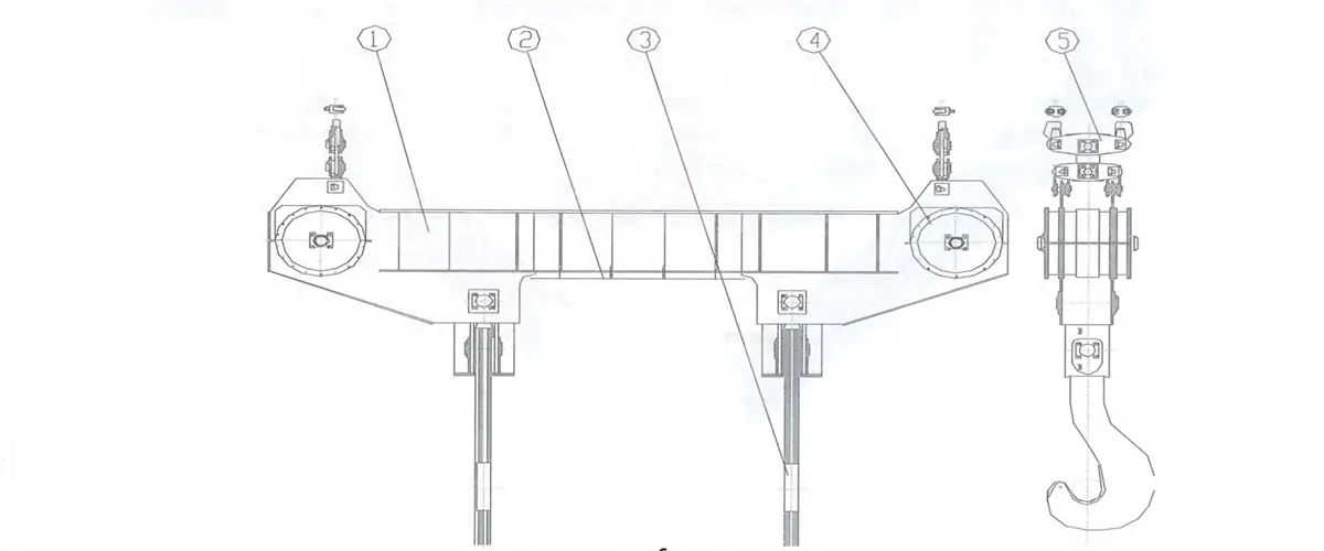
2.5.6.2 Gantry-type laminated plate hook
Kingda ladle crane (or casting crane) Gantry-type laminated plate hook is used to convey the vessel with molten metal and consists of movable pulley block suspended beam, plate hook, thermal insulating device, etc. The lifting steel rope is wound on movable pulley group, the suspended beam is box-type structure, the plate hook is made by multiple hook pieces cut along the rolling direction through riveting and there is wearproof liner at the mouth of hook. According to different lifting weight and functions, there are many forms:
Form l: the suspended beam is configured with movable pulley block, the distance between shank hooks is fixed and the tail end of steel rope is fixed on the balance arm of movable pulley block. Please refer to Figure 2-37.
Form Il: the suspended beam is configured with movable pulley block. The distance between shank hooks is variable and the tail end of stee rope is fixed on the balance arm of movable pulley block. Please refer to Figure 2-38.
Form Ill: the suspended beam is configured with movable pulley group, the distance between shank hooks is fixed and the tail end of steel rope is fixed on the balance arm of movable pulley group. Please refer to Figure 2-39
Form lV: it adopts rotational structure. It consists of movable pulley block, fixed suspended beam, slewing suspended beam slewing mechanism, thermal insulating device, shank hook, etc. The slewing mechanism is set on the fixed suspended beam. During the working, the slewing mechanism will drive the slewing suspended beam to rotate for 90’or 180’. Please refer to Figure 2-40.
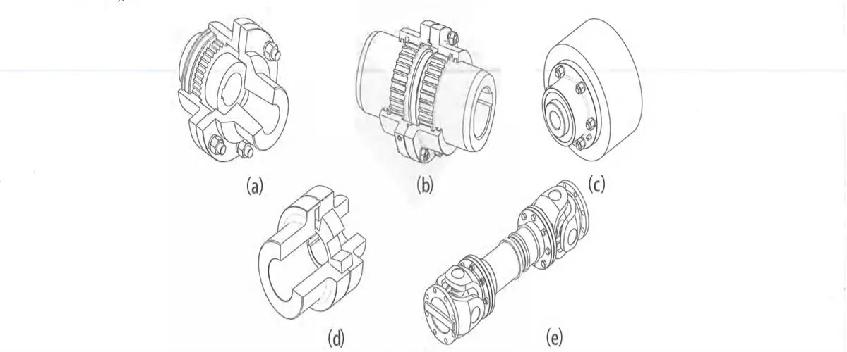
Kingda ladle crane (or casting crane) coupling is mainly used to connect two rotation shafts arranged in coaxial line to deliver torque and compensates light angular and radial deflection. The coupling commonly used by the crane includes straight-tooth coupling (Figure2-41a), crowned-tooth coupling (Figure 2-41b), brake wheel coupling (Figure 2-41c), coupling with elastic spider (Figure2-41d), universal coupling (Figure 2-41e), etc.
Figure 2-41 Coupling
Tooth coupling consists of internal tooth ring of the same number of teeth, flanged half-coupling with outer teeth, etc. Internal &external tooth rings and shaft coupling or brake wheel can also comprise semi-tooth coupling. According to different tooth shapes, outer tooth can be divided into straight tooth and crowned tooth. Outer tooth of crowned tooth coupling is aspherical surface, and the center of the surface is on tooth axis. The backlash in circular tooth is larger than general tooth. The crowned tooth coupling can allow relatively large angular displacement (relative to straight-tooth coupling), and can improve contact conditions of the tooth, improve the capacity of delivering the torque and prolong the service life. During the work. Two shafts of the tooth coupling will generate relative displacement. tooth surface of inner and outer teeth will carry out axial relative sliding periodically, which will certainly result in abrasion of tooth surface and power loss, Therefore, the tooth coupling shall
Work in good lubrication and sealing condition. Coupling with elastic spider consists of two identical half-couplings of protruded claw form and elastic components. It can realize the connection of two half-couplings by virtue of protruded claw support of quincunx elastic component placed on two half-couplings. t’s featured by compensation of relative deflection of two shafts, vibration attenuation and buffering. lubrication-free, etc. When replacing the elastic component, two half-couplings shall move axially. Elastic components can be made by polyurethane or cast nylon.
Universal coupling is mainly used for low-speed shaft transmission and has relatively large angular compensation ability by virtue of the features of its mechanism. the connected two shafts can realize continuous rotation in the condition that the two shafts are not on the same axial line and there exists axial included angle, and deliver the torque and move reliably. The included angles of two axes of the universal couplings in different structure styles are different, generally between 5’-15°
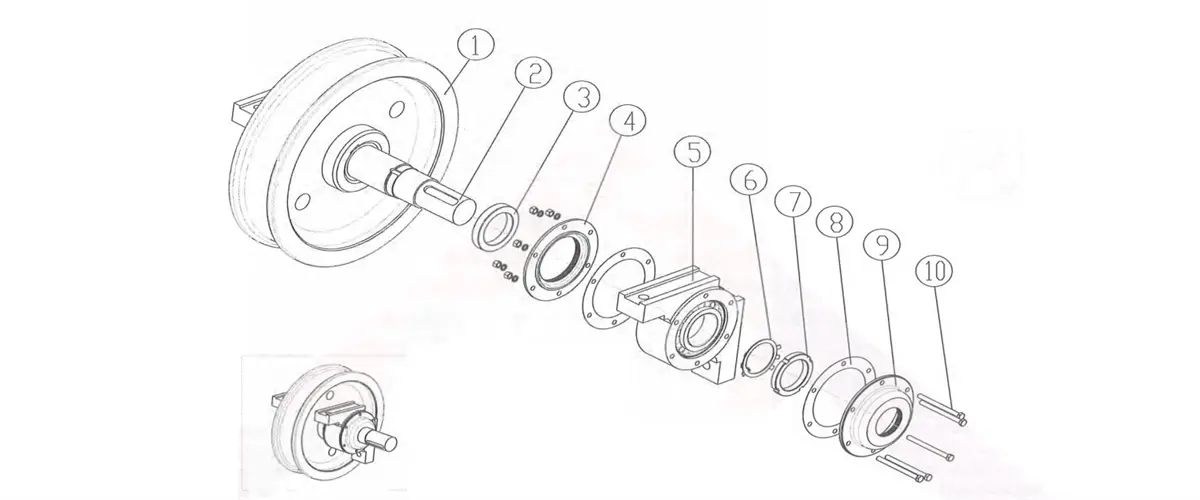
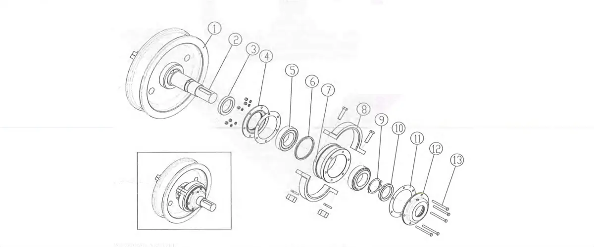
2.5.8 Wheel block
Kingda ladle crane (or casting crane) Wheel block is an important component of operating mechanism and consists of wheel, shaft, bearing box, etc. According to the structural style, it can be divided into angular bearing box (Figure 2-42) and 45’split bearing box
(Figure2-43). The wheels are double flanges.
Figure 2-42 Angular Bearing Box Wheel Block
1-wheel 2-shaft 3-spacer 4-holed cover bush 5-angular bearing box 6-washer7-round nut 8-adjustable pad 9-holed cover 10-fastening bolt
Figure 2-43 45° Split Wheel Block 1-wheel 2-shaft 3-spacer bush4-holed cover 5-bearing 6-spacer bush 7-bearing chamber8-housing of bearing chamber
9-washer 10-round nut 11-adjustable pad 12-holed cover 13-fastening bolt
2.6 Technical characteristics
Please refer to the drawing provided with the equipment for main technical parameters and overall dimension in detail


.WEBP)