The user shall ensure that operation and maintenance personnel have executed relevant regulations of national labor and safety guarantee department strictly during working process. The following information is very important for ensuring kingda ladle crane (casting crane) operation personal’s safety and relevant operation & maintenance:
- 1. The user must ensure that the crane has been inspection and test by professional personnel before initial commissioning and before the reoperation after major repair.
- 2. The user must ensure that the crane must be inspected and tested by professional personnel once per year.
- 3. The user must keep all crane’s results and records during the inspection and test process.
- 4. The crane shall be operated by special personnel, and the operator must fully master relevant knowledge of installation, maintenance and operation manual.
- 5. The user shall ensure that side pulling phenomenon will not happen during the operation.
- 6. The user shall ensure that the crane will not be used to lift he load heavier than the rated lifting weight. When the crane configured with inseparable lifting spreader, the rated lifting capacity shall be the sum of weight of vessel containing the molten metal and the weight of the molten metal. When the crane with separable lifting spreader, the rated lifting capacity shall be the sum of the weight of lifting spreader, the weight of the vessel containing the molten metal and the molten metal.
- 7. Before each shift change, the operator must check if the braking device is intact.
- 8. When operation personnel discoveries any obvious defect on the crane, it’s required to stop using it and inform relevant repair personnel immediately.
- 9. The user shall ensure that no load will be hung on the hook for a long time when the crane is stopped.
- 10. The operator shall ensure that the load can be lifted safely and there isn’t idle personnel in the lifting area.
- 11. Maintenance personnel shall carry out maintenance work only after the main power supply is cut off.
1.3 Personnel requirements
To prevent any accident arising from equipment operation by personnel unqualified, the user shall formulate full set personnel qualification prescriptions, showing detailed assignment responsibility to Driver, maintenance personnel, service personnel, etc. Relevant personnel can only work within their own responsibility range and shall not go beyond the range. The following contents are personnel qualification prescriptions proposed for the user:
- 1. Personnel reliability is the basic condition for working on the equipment.
- 2. It's required to ensure that all workers have reached the required statutory minimum working age.
- 3. The driver must get professional training and serve as a equipment operator only after passing relevant assessment. Only 1 driver is allowed to carry out equipment operation in each shift. The driver shall carry the key of main control switch along with him and shall not hand over the key to any other personnel for storage or place the key in any place arbitrarily.
- 4. Only the personnel by relevant training and getting corresponding qualification can engage in relevant work on the crane.
- 5. During the training process, during the training, t’s required to especially highlight on safety measures required by hazard and safety.
- 6. It’s required to audit regularly personnel qualification every year.
- 7. Responsibilities of the personnel operating and maintaining the equipment must be regulated explicitly.
- 8. Designate an equipment manager, define his responsibility and allow him to refuse to execute the command violating safe operation from the third party.
Please refer to Table 4-1 for labor division to various personnel (V/ means allow, and X means disallow).
| Table 4-1 Personnel Labor Division |
| Work classification |
Trained personnel |
Qualified technician |
Qualified electrician |
After-sales service personnel |
| Equipment operation |
√ |
X |
X |
X |
| Trouble shooting |
X |
√ |
√ |
√ |
| Mechanical fault repair |
X |
√ |
X |
√ |
| Electrical fault repair |
X |
X |
√ |
√ |
| Routine maintenance and repair |
X |
√ |
√ |
√ |
1.4 Injury risk
- 1. Incorrect use.
- 2. Insufficient maintenance and care.
- 3. Failure in reading the safety instructions given in the manual may result in corresponding injury.
- 4. Arbitrary overhaul, maintenance or crossing operations on the Kingda ladle crane (casting crane) without cutting off crane’s main power supply may result in personnel falling.
- 5. Loose clothes, wearing jewelry, etc. operator may be involved in the equipment.
- 6. When the lifting spreader hoists to upper limit position, failure in observation may result in rushing to the top, which will further result in steel rope breaking and lifting spreader falling.
- 7. Taking nicotine, alcohol or medicine may affect the response ability, and personnel in such state cannot allow to operate the crane.
- 8. In ground remote control mode, the operation personnel shall keep a safe distance with the objects for lifting.
1.5 Dangerous area
Installation and maintenance personnel must learn about dangerous area of the Kingda ladle crane (casting crane) and remember equipment’s dangerous area to prevent personal injury. Please refer to the following table for crane’s dangerous working area.
| Table 4-2 Crane Dangerous Working Area |
| Dangerous area |
Specific part |
Precautions |
| Injury risk area |
Hoisting mechanism |
Pay attention to the hoisting mechanism in operation |
| Main hook and auxiliary hook |
Pay attention to main & auxiliary hook devices in operation |
| Travelling mechanism |
Pay attention to travelling mechanism in operation |
| Falling risk area |
Inclined ladders access to the equipment |
Hold the railing tightly |
| Platform edge next to the railing |
Do not stretch the body out of upper part of the railing |
| Electric shock risk area |
Transformer room, inside the electric room and electrical cabinet, external electrical element, crane sliding wire |
It is forbidden to touch the electrical elements. |
| Flammable materials dangerous area |
Surrounding the lubricating pump |
It is forbidden to smoke or have open fame, and check if the line is ageing regularly. |
During crane operation, all personnel shall not stay in the following dangerous areas:
- ►Trolley travelling area;
- ►Hoisting mechanism working area
- ►Under the working area of main & auxiliary hooks
- ►Crane operating area of the crane
1.6 Violation operations (not limited to the following conditions)
- 1. The load exceeds the rated lifting capacity.
- 2. Side pulling phenomenon during the load.
- 3. Lift or transport any person.
- 4. Inching operation frequently.
- 5. Bulge, strand breaking or other damage happens to the steel rope, but it isn’t replaced.
- 6. Operate the equipment deliberately to trigger emergency switch.
- 7. Use the equipment with no stop when there is any abnormal condition or abnormal noise.
1.7 Before the operation
The operator shall check the motor, brake, steel rope, safety device, etc. according to daily inspection requirements, and remove any fault in case any abnormal condition is discovered.
.png)
.png)
1.8 During the operation
- 1. During first time lifting in each shift (or when the load reaches maximum lifting capacity), it’s required to lift the object to0.5m from the ground and put down again to check the brake performance, and then carry out operations after it's confirmed to be reliable.
- 2. It is required to carry out operation according to the uniform command signals.
- 3. It is forbidden to realize crane stopping by limit switch.
- 4. It is forbidden to push another crane by crane.
- 5. It is forbidden to under the object when the crane is lifting.
- 6. Any person shall not cross one crane to another crane.
- 7. The operator shall pay close attention to crane moving direction and check if there is any person or barrier surrounding the crane.
- 8. The crane shall be started step by step, before the mechanism stops operation completely, it is forbidden to put the controller to reverse position directly from veering position to realize braking.
1.9 After the operation
- 1. Hoist the lifting spreader to near the maximum point, park the Kingda ladle crane (casting crane) in the designated position, put the control handle to zero position and cut off the main power supply.
- 2. Cut off the remote control power supply (if any) and place it in the designated position.
- 3. Carry out crane routine maintenance.
- 4. Carry out shift change work.
1.10 Safety device
Safety device is a necessary setting to prevent Kingda ladle crane (casting crane) accident, including limiting travel length and working position, preventing crane overload, interlocking protection device, etc. The crane shall be configured with the following devices according to different requirements:
1.10.1 Emergency stop button
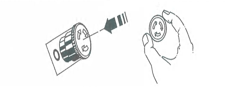
Mushroom-shape emergency stop button is configured on remote controller or linkage station. During the operation process, in case any operating action of hoisting, long travel and cross travel is inconsistent with the command or any other accident happens, it’s able to press the [emergency stop button] to stop all actions, then find out corresponding reasons
- ♦ Press the red emergency stop button => cut off the power supply of crane’s main circuit
- ♦ Rotate the emergency stop button clockwise => release the button and the equipment will be started.
Figure 4-1 Emergency Stop Button
1.10.2 Hoisting limit
Hoisting mechanism employs two different structure limiting devices - rotary type and gravity hammer type, to ensure safe and reliable use. When load handing device lifts to the extreme position regulated in the design, both the two switches can cut off hoisting power supply automatically. When load handing device lowers to the lower extreme position, rotary limit switch can cut off lowering power supply (hoisting height > 20m) automatically and guarantee that it can cut off power source automatically when load hanging device lowers to the limiting position. ln addition, the steel rope shall wind the reel for at least 2 rings regulated in the design.
After motor’s power supply in above moving direction is cut off, it can still can work as the power supply for the motion in reverse direction, the mechanism can move in reverse direction.
The rotary-type hoisting limit switch adopts adjustable-mechanical memory structure. lt is mounted at one end of the reel, consists of high-precision reducer of large transmission ratio, mechanical memory mechanism synchronous with its output shaft and microswitch, can control the hoisting mechanism lifting and lowering limit by acquiring rotation rings of the reel.
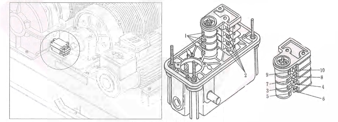
Flgure 4-2 Rotary-type Limit Device
1-member cam 2-circuit breaker 3,5,79-cam 4,6,8,10-breaker contact
Gravity hammer type limit switch consists of LX limit switch and gravity hammer. The gravity hammer is hung on the steel rope and connected with bump bar. When the lifting spreader lifts to upper extreme position, cross bar will be jacked up and the balancing hammer on limit switch will turn on the limit switch under the effect of gravity to cut off hoisting mechanism power supply. During the installation, it’s required to pay attention to placing the bump bar in horizontal level, in case the oblique angle is too large, when the crane is lifted with no load, it may make the lifting spreader swing to the lower end of vertical bar due to swing. When it’s lifted continuously, the vertical bar will be bent by jacking and the plummet still fails to uplift. As a result, the rope will be broken. It is required to check and lubricate the hinged shaft connected to the cross bar and vertical bar frequently, to prevent rusting. During gravity hammer starts action, the master contactor will be powered off. After the handle returns to zero position, it is able to close the master contactor again and hoisting mechanism can carry out lowering operation.
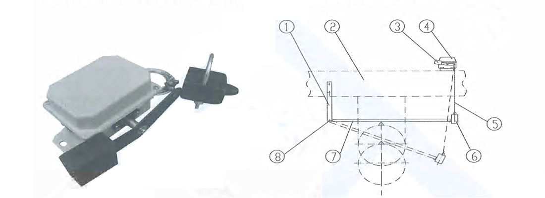
Figure 4-3 Gravity hammer type Limit Device
1-vertical bar 2-trolley frame3-balancing plummet4-limit switch5-pulling rope6-plummet7-cross bar 8-hinged shaft
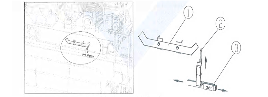
1.10.3 Travelling limit
Trolley travelling limit switch adopts mechanical limit and is fixed on adjusting pedestal at both ends of the bridge frame. When the safety ruler on the side of the trolley touches the contact of limit switch, it can disconnect the control loop, and the mechanism can act only during the operation in reverse direction.
The contact of the limit switch can be adjusted along the arrow ‘s direction.
Figure 4-4 Mechanical Operation
1-Limit-safety ruler 2-limit switch 3-adjusting pedestal
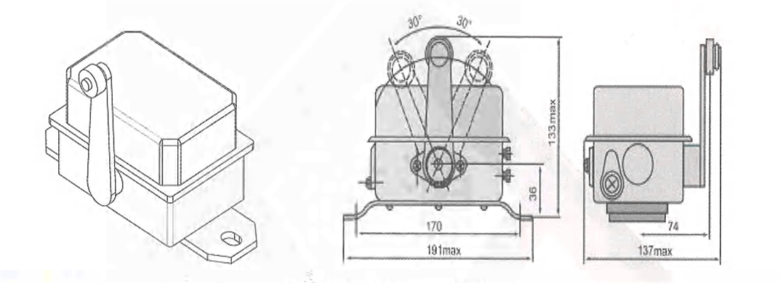
Kingda ladle crane (casting crane) long travelling limit switch adopts mechanical limit and is fixed at both ends of end beam on cab side. When the safety ruler mounted on the side of the workshop touches the contact of limit switch, it can disconnect the control loop, and the mechanism can act only in the reverse direction.
Figure 4-5 LX10-12 Limit Switch
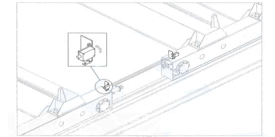
1.10.4 Anti-collision device (optional)
According to requirement, the Kingda ladle crane (casting crane) can be configured with photoelectric anti-collision device to prevent collision of multiple cranes running on the same track. Please refer to Figure 4-6 for arrangement form. When two cranes approach to certain safety distance, A crane transmitter sends out optical wave will be received by crane B receiver, electrical signal will be generated through phototube. After wave shaping and amplification, the relay will act, the buzzer will give an alarm and cut off the operating mechanism power supply automatically. Two adjacent cranes shall be configured with 1 set, to realize interaction respectively. Common photoelectric anti-collision device includes laser anti-collision device and infrared anti-collision device. Please refer to the operation manual provided with the equipment for its installation and maintenance.
Figure 4-6 Anti-collision Device
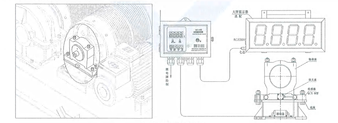
1.10.5 Overload limiter and electronic scale
Overload limiter is bearing pedestal form and mounted at the end part of the reel. When actual lifting weight exceeds 95% of the rated lifting capacity, it will give an alarming signal; when it exceeds 105% of the rated lifting capacity, it will give continuous audible and visual alarms. The relay contact will act after time delay of 1-2s to cut off the lifting power source automatically. Lt only allows the mechanism to make lowering motion, so as to play the role of safety protection.
Overload displayer is configured inside the cab and it’s also able to arrange a large screen displayer on the bridge frame as required.
Figure 4-7 Overload Limiter
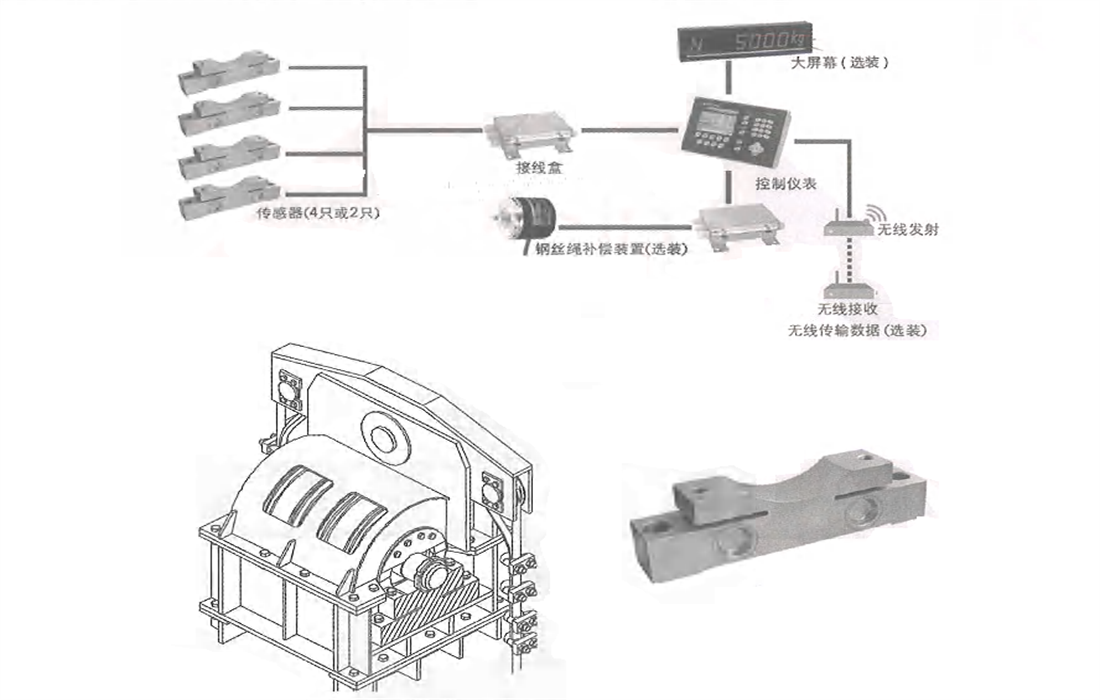
Apart from weighing function, electronic scale still have overload protection function. The sensor mainly employs bridge-type shear beam structure and is mounted under the reel bearing pedestal, under the fixed pulley, under the trolley frame or inside the wheel bearing box. lt is generally mounted under the fixed pulley shaft.
Figure 4-8 Fixed Pulley Type Electronic Scale
| Precautions |
- Overload limiter has gone through the calibration of the rated load before ex-factory. During the overload test carried out or service site, it is required to shield the overload limiter and recover it after the test is finished.
- In case the set value of overload limiter is discovered to be much different from the actual condition, please contact the manufacturer or qualified maintenance technician to carry out setting of overload limiter again.
|
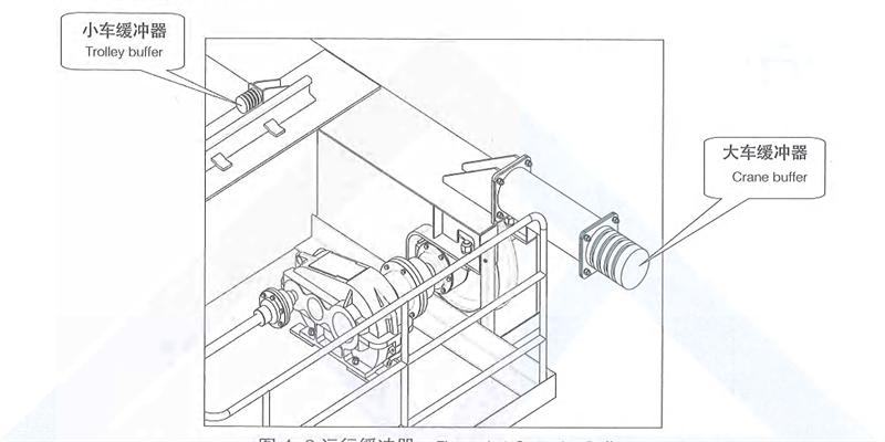
1.10.6 Buffer
Both Kingda ladle crane (casting crane) long travelling mechanism and trolley cross travelling mechanism are configured with buffer, which can alleviate the impacts arising by the collision of the crane bridge or trolley when it moves to the end point or the collision of two cranes, it can absorb the collision energy effectively. For buffer’s material, there are PU buffer. casting compound elastomer buffer or spring buffer.
Figure 4-9 Operation Buffer
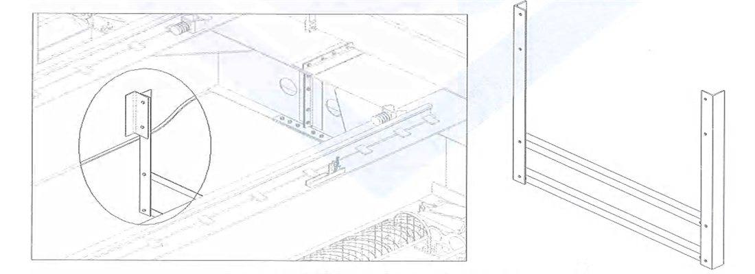
1.10.7 Sliding wire protection device
Hook fence is configured on power supply sliding wire side, which can prevent the lifting spreader or steel rope from bumping the sliding wire due to shaking or swinging when the trolley moves to the limiting position.
Figure 4-10 Hook Fence
1.10.8 Sliding wire inspection device
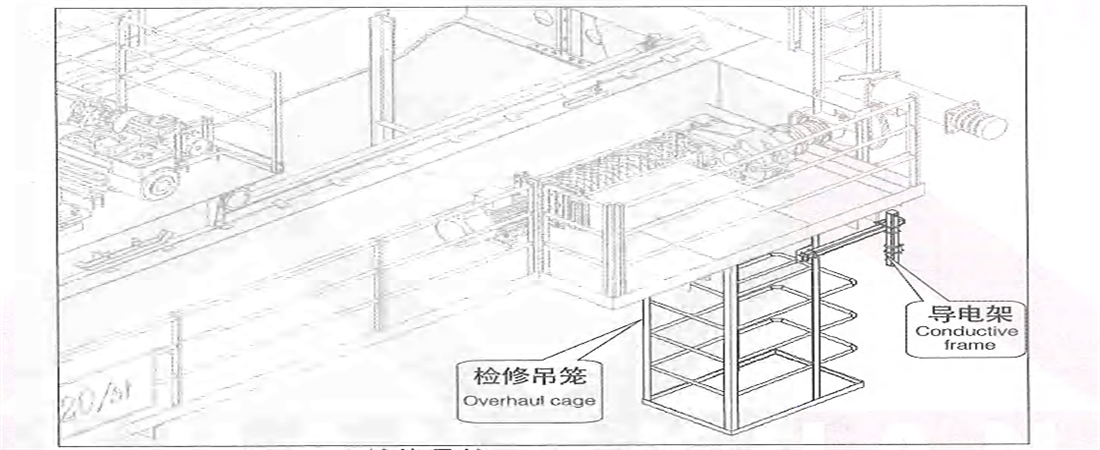
When the power supply and Kingda ladle crane (casting crane) cab are not in the same side, inspection cage will be configured on power supply sliding wire side, mounted under the walking board on transmission side, and equipped with crane conductive frame. When power supply sliding wire breaks down, the maintenance personnel can enter into the cage through access hole on walking board to carry out repair
Figure 4-11 Inspection Cage
1.10.9 Rail clearing device
Rail clearing device is set in front of Kingda ladle crane (casting crane) travelling wheel with a distance of 10mm away from the rail surface, can clear away the barriers deposited on the rail.
Figure 4-12 Rail Clearing Device
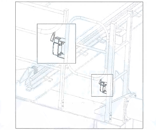
1.10.10 Door switch
Cab platform door, boarding steering platform door and end beam railing door are all configured with door switch which has interlocking protection function, namely. when any door is opened. the Kingda ladle crane (casting crane) power supply and trolley travelling mechanisms will be power off.
Figure 4-13 Door Switch
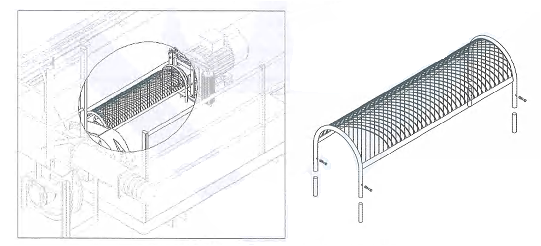
1.10.11 Protective cover
The exposed transmission shafts on Kingda ladle crane (casting crane) are all configured with nets protective cover by bolt connection.
Figure 4-14 Protective Cover
1.10.12 Protective railing
Walking board and access area are configured with railing with the height of 1,050mm. Three rows of cross bars are set and there is skirt board under the railing.
1.10.13 Overspeed protection
Overspeed switch is mounted at hoisting motor end or reel end to limit maximum speed of the motor or the controlled device driven by the motor so that it can disconnected with the circuit quickly, ensure equipment’s safe operation. It can be used as emergency protective device for speed control. The specific principle is as follows: it makes use of rotor’s centrifugal force to promote tripping mechanism to realize contact action, so as to disconnect the circuit. When the speed of the controlled device is increased suddenly due to any sudden cause ,reaches the contact action’s speed, the gravity hammer will overcome the spring force to shift in radial direction under the effect of centrifugal force to hit the cambered surface of controlling device, so that the transient impact force will facilitate the controlling device to rotate along its spindle As a result, the slide bar will be released and move quickly rightwards under the effect of spring, the travel switch will also correspondingly and the task of disconnecting, the circuit will be finished.
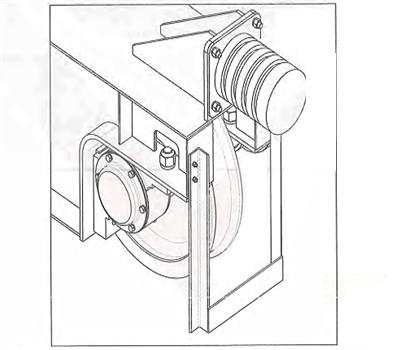
1.10.14 Safety brake (optional)
Kingda ladle crane (casting crane) for hoisting the molten metal will be configured with electromagnetic (as shown in the figure) or hydraulic disk-type safety brake at the end of main hoisting reel. When the working brake or transmission part of the hoisting mechanism fails, emergency safety braking can be used cooperating with overspeed switch. During normal operation of the crane, safety brake will be powered on prior to the moor and always be in power-on & switching-off condition. When overspeed switch detects any overspeed signal or emergency stop button acts, the power supply of hoisting mechanism will be cut off, working brake will be switched on, safety brake will be powered off and switched on after time delay.
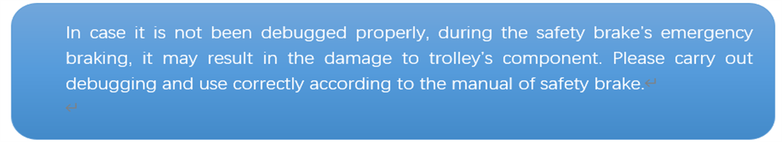
When a part on transmission chain fails, safety brake will realize braking prior to the working brake. At this time there will be large impacts, which may damage the transmission component.
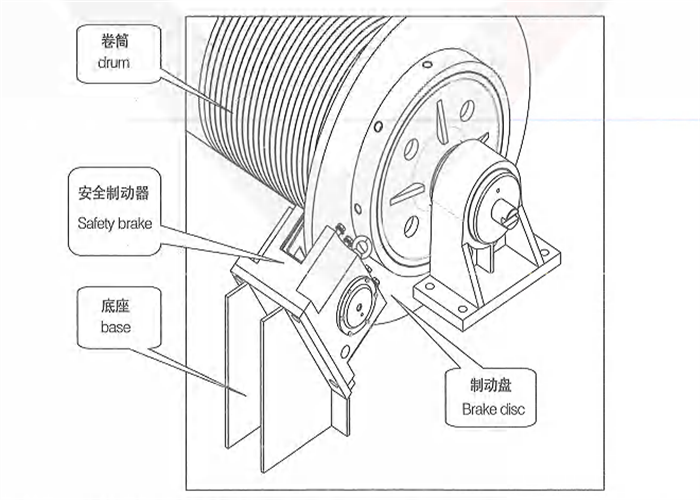
Figure 4-15 Electromagnetic Disk-type Safety Brake
1.10.15 Thermal insulation protection
To reduce the thermal radiation of molten metal to structural members, thermal insulation layer is configured on the bottom cover plate of the main beam and under the gantry-type lifting spreader.
1.10.16 Other protection
In addition, the Kingda ladle crane (casting crane) has also been configured with various electric protections:
- 1. overcurrent protection- each mechanism’s motor has two-phase overcurrent relay separately. Another phase can realize protection by protecting main overcurrent relay inside the protection box, and action current of each relay is 2.5 times of the rated current of the protected motor
- 2. Line protection-all external lines have short-circuit or grounding protection.
- 3. No-voltage protection-after the power supply is disconnected, all electric devices involving in the safety and inappropriate to be started automatically shall be in power-off, prevent automatic action of the mechanism after the power supply is recovered.
- 4. Zero position protection-in case the mechanism stops operation due to any fault or no voltage during the operation, when the power supply is recovered again, the mechanism can’t act automatically. The crane can be restarted only by placing the control handle in zero position manually and pressing the butt on “start” again.
- 5. Interlocking protection-railing door and cab door are configured with door switch. When any door is opened, it is required to cut off power supply of crane’s corresponding mechanism immediately. When multiple control modes are employed, each control points shall be interlocked mutually to guarantee that only one control point is in working condition at any moment, all control points are configured with emergency power-off device.
- 6. Forward/reverse contactor protection- all lifting mechanism who’s hoisting motor power is no less than 30KW be configured with forward/reverse contactor protection. When the contactor fails, it will control a time relay by zero position control and series connection of NO contacts of forward and reverse contactors, connect NC point of time relay to the circuit of main contractor; Disconnect the master contactor (power failure of main circuit) quickly after the pre-set time, thus it can play the role of protection.
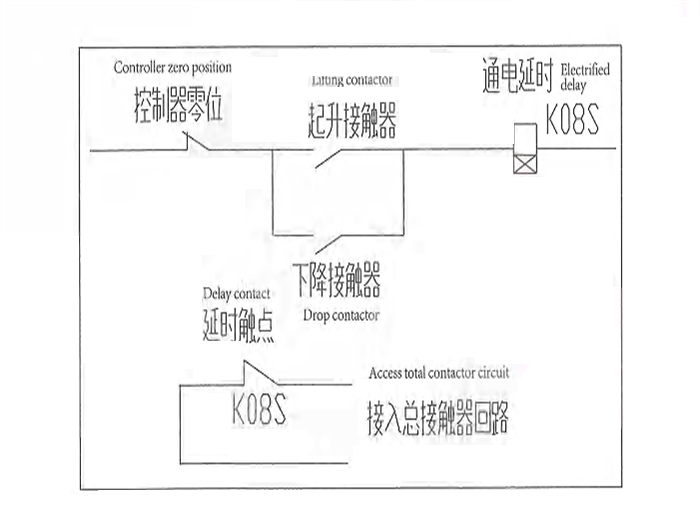
Figure 4-16 Schematic Diagram of Forward/Reverse Contactor Protection
Operation alarm (optional) -During the operation of the Kingda ladle crane (casting crane), the alarm will make a sound and give a signal with lamp flickering to prompt relevant personnel to pay attention.
| Special warning |
-- The safety rules are formulated for the purpose of preventing personal injury and reducing the damage of the crane and site facilities.
--For personal safety of you and other personnel and the safety of crane and site facilities, please abide by the safety rules strictly. --As to personal injury and the damage of crane and site facilities arising from the safety rules, the company will not bear any liability. |
2. Ladle Crane Installation and commissioning

2.1 Equipment storage
Installation work shall be completed within 6 months upon the equipment is transported to site, and then normal maintenance of the equipment shall be carried out. In case the user puts the equipment idle for a long time due to other cause, it’s required to storage and maintenance well.The user shall count and maintain the idle goods every 2 months since the equipment is transported to site (including rust removal and paint repair of the damaged surface, rust protection of high-strength bolt joint surface, grease filing and dustproof & waterproof treatment of bearing box, waterproof and damp-proof treatment of electrical & hydraulic elements, etc.). Make sound records of the damage and maintenance conditions for future reference,
It is required to store the equipment according to the storage conditions specified on the packing case. in case there isn’t such storage condition, the storage shall be carried out according to the following regulations:
- 1. The bundled parts in steel structure shall be placed in flat field with high elevation and no water. The equipment shall be cushioned by wood to keep a certain distance from the ground. Ultrahigh objects that may fall down easily shall be reinforced and configured with warning signs with prompt words such as “Danger of falling down, please keep far away", etc. in surrounding area. As to bearing rotation surface and high-strength bolt joint surface, it is required to check if the waterproof or antirust treatment is damaged. ln case it’s damaged, it’ s required to repair it timely to prevent water, dust, rust, etc.
- 2. The objects transported in packing case shall be placed in the field with a shed, no rain and no water to prevent rainwater from flowing into the case to damage internal elements.
- 3. Packing case of electrical elements and hydraulic elements shall be placed in a dry room to prevent dampness of electrical elements, etc. As to the box with strict requirements on dampness, it’s required to check the condition of drying agent regularly. ln case it’s out-of-date, it shall be replaced immediately.
2.2 Out-of-box audit
5.2.1 Check if the model, specification and quantity of Kingda ladle crane (casting crane) accessories comply with relevant requirements of technical documents according to the packing list, and check if there are complete random documents.
5.2.2 Check if there is deformation, damage or rust on Kingda ladle crane (casting crane).
5.2.3 Check and confirm that the steel rope doesn’t’ have any damage, bending, twisting or looseness phenomenon which can influence its performance and safety;
5.2.4 Check if the line of electric box (cabinet) is correct by multimeter to prevent the looseness of wire end during transportation process;
5.2.5 Clear away the oil stain or antirust oil on treading surface of the wheel.
2.3 installation
2.3.1 Installation method
Mobile crane shall be used for the installation. Please refer to installation Construction Scheme for specific installation steps of Kingda ladle crane (casting crane).
2.3.2 Assembly of main beam and end beam
As to the assembly of main beam and end beam, there are bolt connection or pin connection according to different structures.
- 1. Place the driving span and following span on the rail respectively, and fix both ends temporarily
- 2. Assemble joint bolt or hinge pin of the end beam as shown in the figure;
- 3. Tighten the bolt by the torque suggested in Article 8.6,
- 4. After the assembly is completed, measure the crane’s span limit deviation
△S: when △S ≤10m, △S= ±2.5mm; when △S>10m, △S=±[2.5+0.1(S-10)]mm;
- 5. Ensure that the difference of diagonal lines measured with the datum point for wheel installation isn’t larger than 5mm
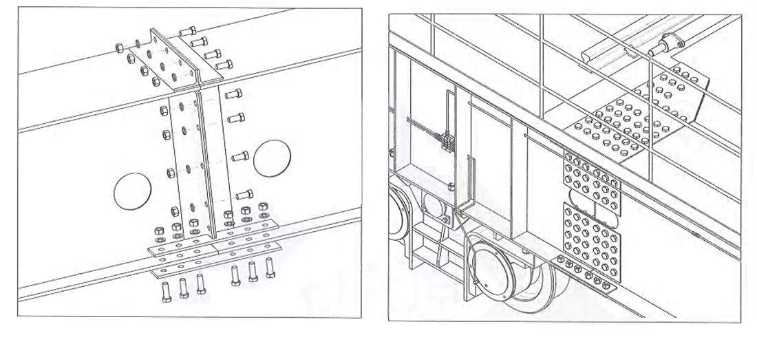
Figure 5-1 End beam connection bolted connectionFigure 5-2 End beam connection pin shaft connection
1-fastening bolt 2- shaft end baffle 3-hinge pin 4- concave locating plate 5-convex locating plate
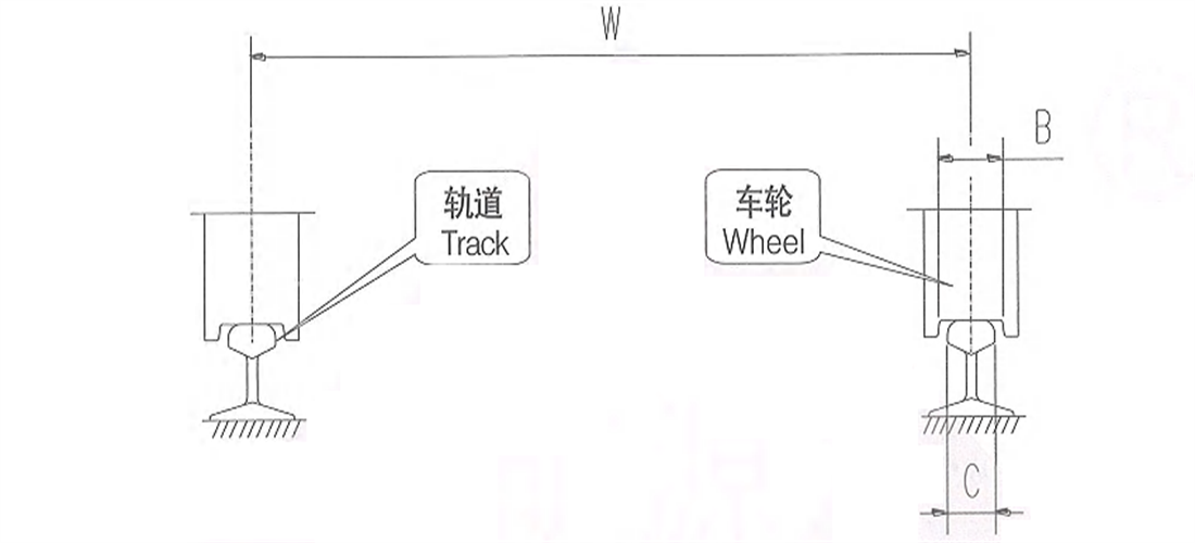
2.3.3 Installation of hoisting trolley
- 1. Check if the width of wheel groove of the trolley (B) is consistent with the width of treading surface of the rail (C);
- 2. Check and ensure that center distance of the rail (W) on the main beam is consistent with the trolley rail gauge.
- 3. Hoist the trolley on the track of main beam and check vertical & horizontal gradient of the wheels.
- 4. Check and ensure that the pedestal of conductive frame is on the same side with feed line of the trolley.
-
Figure 5-3 Installation of Trolley
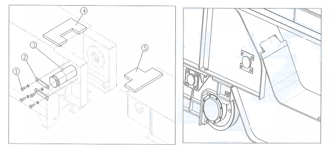
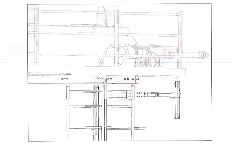
2.3.4 Installation of maintenance cage and conductive frame
- 1. Insert the maintenance cage between two channel steels under the walking board, and fix the bolt
- 2. Fix the conductive frame on maintenance cage’s connecting plate by U-shape bolt as shown in the figure;
- 3. After conductive frame’s position is adjusted well, tighten the bolt by the torque suggested in Article 8.6.
Figure 5-4 Installation of Maintenance Cage
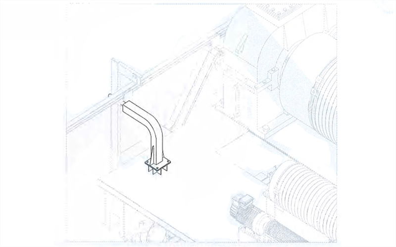
2.3.5 Installation of trolley conductive frame
- 1. Fix the conductive frame on trolley’s support beam as shown in the figure;
- 2. Tighten each bolt by the torque suggested in Article 8.6 after the position is adjusted well.
Figure 5-5 Installation of Conductive Frame of Towrope Trolley
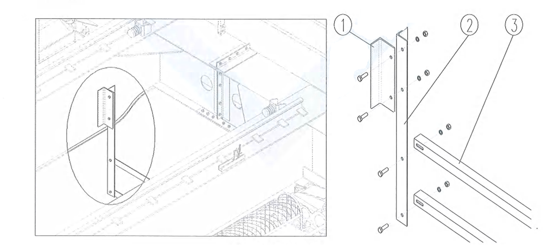
2.3.6 Hook fence Installation
The hook fence shall be mounted at the end part of main beam near the sliding wire side to prevent hook or steel rope collision against the sliding wire.
Figure 5-6 Installation of Hook Fence
1-angel iron support 2-angle iron vertical bar 3-angle iron cross bar
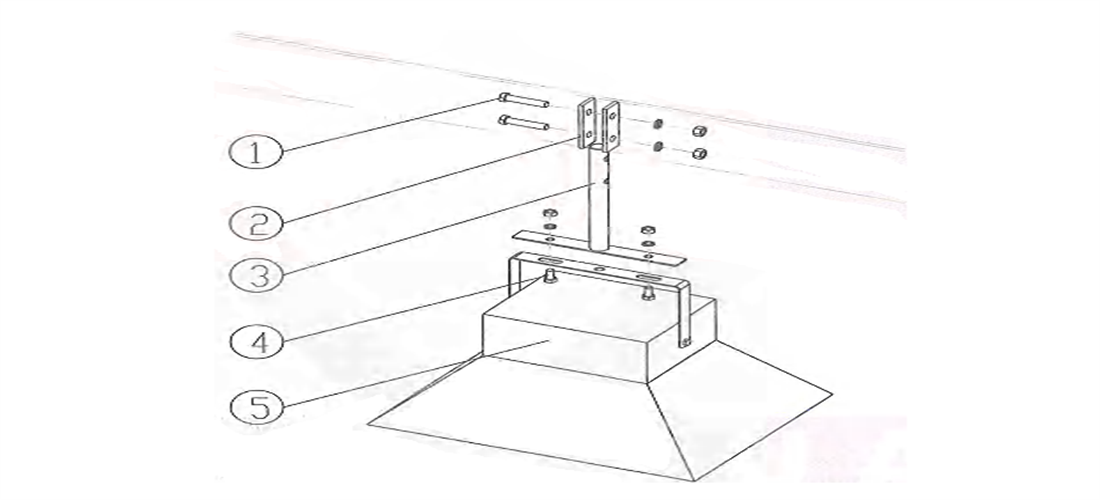
2.3.7 Installation of headlight under bridge frame
Bridge head light frame shall be mounted under the walking board on transmission side for operation illumination. The quantity shall be decided according to different span.
Figure 5-7 Installation of Headlight
1-fastening bolt 2-fixing plate 3-light holder 4-fastening bolt 5-floodlight
2.4 Hoisting limit switch commissioning
Hoisting limit switch is mounted at the end part of the reel and directly driven by reel shaft. When the reel works, the number of rotating rings will be recorded by the limiter. When hook pulley block is a checked distance from the trolley chassis or the ground, the lifting or lowering will be stopped.
Figure 5-8 Rotary Hoisting Limit
1-memory cam 2-microswitch 3,5,7,9-cam 4,6,8,10-breaker contact
The adjustment shall be carried out according to the following steps
- 1. Remove upper housing, check and tighten 2-M3 x 55 screw.
- 2. Loosen M5 nut.
- 3. Operate the lifting spreader to the designated position as required. At this time, corresponding microswitch controlling the action of the mechanism shall switch over instantly, namely, adjust corresponding adjusting axis (Z) to make the memory cam (T) to press the contact of microswitch (WK).
- 4. Tighten M5 nut. (The nut must be tightened, otherwise, it will generate member disorder).
- 5. The lifting spreader will go through idle running repeatedly for several times to verify if the memory position is accurate (in case there is any error, repeat above steps).
- 6. Confirm that the position complies with relevant requirements, fasten M5 nut and mount the housing7) After the mechanism works normally. it’s required to check if the memory control position is changed frequently for the convenience of timely correction
3. Ladle Crane Test run
Before the Kingda ladle crane (casting crane) is used, it’s required to carry out the following inspection and commissioning at least.
3.1 No-loading inspection
3.1.1 Check the connection of electric devices
Check and ensure that the connection of electric devices is consistent with wiring diagram. Check the wiring mode to ensure that the wire will not result in any barrier due to intersection of wiring structure during crane’s action.
3.1.2 Check working noise
Judge if there exists any installation error according to the noise during the hoisting and operation.
- ln case the hoisting motor gives out loud intermittent noise, the problem may happen to the power supply. It is required to check and correct phase sequence of power supply.
- In case the operation action generates loud noise and drastic vibration, it may be resulted from wheel “rail gnawing”. It is required to check the cooperation condition of wheel and track.

3.1.3 Hoisting limit switch inspection
check the working condition of limit switch by operating the hook to upper limiting position and lower limiting position.

3.1.4 Travelling limit switch Inspection
Adjust the triggering position of limit switch. Check the working condition of limit switch by operating ladle crane (casting crane) to trigging position.

3.1.5 Operation inspection of hook pulley
Check and ensure that the pulley can rotate freely
3.1.6 Steel rope inspection
Check and ensure that the steel wire isn’t damaged.
Check and ensure that the steel rope enwinds the reel and pulley in the correct way.
Check the fixing condition of steel rope at the end.
- Enabling load of new steel rope shall be about 10% of the rated load, and the load shall be lifted to the total lifting height for 5-10 times.
3.17 Brake operation inspection
Check and ensure that hoisting brake can work normally in both lifting and lowering directions.
3.2 Inspection of the rated load
3.2.1 Inspection of motor current
Check motor current condition of each phase during hoisting action process with the rated load
-The current in all phases shall be balanced and shall not exceed the rated current of the motor
3.2.2 Bridge long travelling mechanism inspection
Check and confirm that acceleration and braking actions of the operating mechanism can be carried out successfully. Operate it for at least 3-5 times along the whole length of the beam. Remove the paint falling off on the track.
3.3 Overload condition inspection
Check the working condition of overload protection device in overload (110%-125% of the rated load) condition.
-When the load exceeds triggering load of overload protection device, overload protection must be able to prohibit the hoisting action effectively.
3.4 After the inspection is finished
3.4.1 Clearing
Check and ensure that all tools and extra materials used in installation period have been cleared away from ladle crane (casting crane) and rail.
3.4.2 User training
Guarantee that operation Kingda ladle crane (casting crane) personnel and competent personnel learn about the necessity of user training
3.4.3 Delivery documents:
Check the documents delivered with the equipment. Ensure the correctness of document contents, and the consistency of reference data in the documents with the data on the nameplate.
Compile ladle crane (casting crane) test run records and keep the records together with other crane documents.