Kingda Ladle Crane Operation Manual - Part Ⅱ Electrical Control System
DATE: Mar 5th, 2022
Read:
Share:
1. Ladle Crane Electrical control system
1.1 Overview
Kingda ladle crane (casting crane) enables the objects to realize lifting, lowering and horizontal movement in 3D space through hook or other load handing device by intermittent and repetitive work modes. Its electric devices mainly consist of control system, hoisting mechanism, long traveling mechanisms, cross travel traveling mechanism, low-voltage distribution system, operating equipment and auxiliary equipment for communication, lighting and air conditioning. etc.
Kingda ladle crane control employs regular series resistance or stator variable voltage control or frequency inverter speed control system.
1.2 Power supply
1.2.1 In normal working conditions, power system voltage fluctuation in the joint area of crane’s feeding line shall not exceed + 10% of the rated voltage.
1.2.2 The power supply is three-phase AC (three-phase four-wire system), the rated frequency is 50Hz or 60Hz, common rated voltage is 380V or 415V and can also be 660V, 1KV, 3kV, 6kV or 10KY according to actual demand.
1.3 Impacts on environment and energy
When start the relatively high-capacity mechanism, it will result in power grid transient shock and voltage drop to relatively low capacity, and even can affect normal operation and starting of the equipment connected with the same power supply. As to series resistance or stator voltage control system, in case it works at a low speed, it will increase the slip loss, increase harmonic wave of the circuit and reduce power factor.
1.4 Power feeding mode
1.4.1 Lingda ladle crane (casting crane)’s feeding device can employ angle iron sliding wire, rigid body sliding wire, etc.
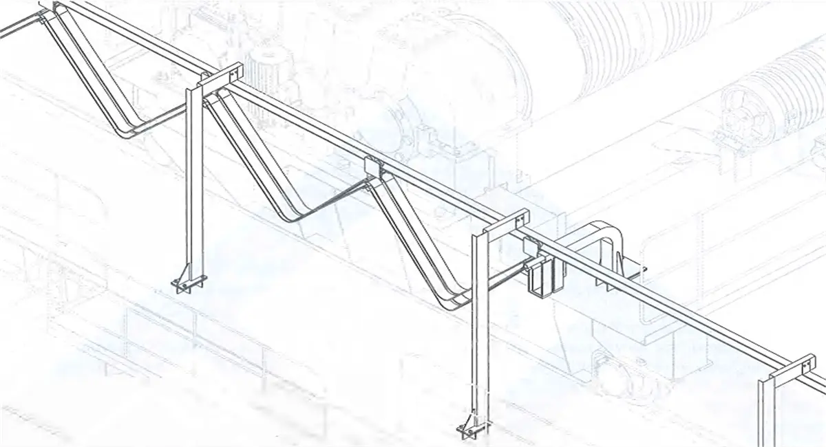
1.4.2 trolley’s feeding device can employ cable pulley form. namely. flexible flat cable will be imported through suspended cable pulley and move along the trolley on the joist steel or deformed steel as the slide way. The cable festoon employs flat cable. To prevent high temperature radiation, the festoon steel or deformed steel shall be arranged inside the walking board.
Figure 3-1 Cable Pulley Power Feeding
1.5 Power distribution system
Power distribution system is used for power distribution and circuit protection of the ladle crane (casting crane), and mainly consists of power distribution protection cabinet (panel), transformer and corresponding operation indication devices, such as key switch, ON/OFF button, emergency stop button, indication device, etc.
1.5.1 Power distribution protection cabinet (panel)
1.5.2 Main power circuit of power distribution protection cabinet (panel) is configured with main circuit breaker.
The main circuit breaker has electromagnetic trip and undervoltage (shunt) trip control functions. When the rated current of electromagnetic tripper is larger than the ladle crane’s rated working current, or the setting value of electromagnetic trip current is larger than ladle crane’s maximum working current, main circuit breaker can break the crane’s maximum short circuit current. When short circuit happens low-voltage line short circuit or power supply emergency disconnecting switch is pressed, the main circuit breaker will trip and disconnect power supply in emergency condition. When line voltage is lower than 85% of the rated value, the main circuit breaker will trip through undervoltage (shunt) trip coil to satisfy driving power supply’s minimum voltage and prevent automatic reclosure when power-on again after the power failure. Power light will display the opening/closing power supply condition.
1.5.3 Power supply circuit is configured with main contactor.
Power supply contactor is used to connect and disconnect the power supply, Unless the ladle crane (casting crane) stops normally, it can disconnect the power supply of all driving mechanism and brake through control system when it is in mechanical and electrical failure conditions.
1.5.4 Lighting power supply will be powered separately.
1.5.5 Each branch circuit for power distribution is configured with branch circuit breaker and over current protective relay (there is no over current relay when control panel is employed). each mechanism’s branch circuit of dynamic, control and auxiliary power supply employs circuit breaker or overcurrent protective relay. When three-phase power circuit employs phase sequence protection, it will have open-phase protection function.
1.5.6 Power distribution protection is configured with actuation indicator light for power supply contactor.
1.6 Drive control equipment
1.6.1 Composition
Kingda ladle crane (casting crane)’s driving device generally consists of the motor, brake, drive control cabinet (panel), resistor, operating devices (button, linkage station, master controller) limit switch, etc.
1.6.2 Main hoisting mechanism
1) Main hoisting motor
2) incremental pulse encoder, as a speed feedback element (or frequency feedback), can realize closed-loop speed control (optional).
3) Overspeed switch serves as overspeed protective element.
4) Rotation limit switch can provide lifting and lowering stop position signals
5) Gravity hammer limit switch serves as over-load operation protective element
6) Load cell can provide load detection signal to carry out over-load protection
1.6.3 Auxiliary hoisting mechanism
1) Auxiliary hoisting motor
2) Incremental pulse encoder, as speed feedback element can realize closed-loop speed control(optional).
3) Overspeed switch serves as overspeed protective element (optional).
4) Rotation limit switch can provide lifting and lowering deceleration and stop position signals.
5) Gravity hammer limit switch serves as over-load operation protective element.
6) Load cell can provide load detection signal to carry out load protection.
1.6.4 Trolley and crane bridge travelling mechanisms
1) Motor(multi-motor)
2) Incremental pulse encoder or frequency, as speed feedback element, can realize closed-loop speed control(optional).
2) Thermal relay or circuit breaker serves as motor overload or overcurrent protective element
3) Travel limit switch can provide stop position signal.
1.7 Lighting and auxiliary devices
1.7.1 Lighting
Under bridge lightings employs LED shockproof light and the quantity of lights will be determined by the span. Indoor lighting employs energy-saving type fluorescent lamp.
Lighting transformer is configured. The lighting transformer employs single-phase three-coil system and can provide AC220V and 36V power supply for the whole equipment.
1.7.2 Inspection socket
The cab is configured with one AC 220V (two-jack/ three-jack socket) and one AC 36V (two-jack socket).
1.7.3 Communication
1) Foot switch
2) Alarm device (optional)
3) Audible and visual alarm (optional)
4) During Kingda ladle crane (casting crane) operation, the driver can remind of ground operation personnel or other relevant operation personnel through above device.
1.7.4 Warming and cooling (optional)
The cab is configured with 1 air conditioner or industrial air coolers, Electric room is configured with 1 or 2 industrial air coolers.
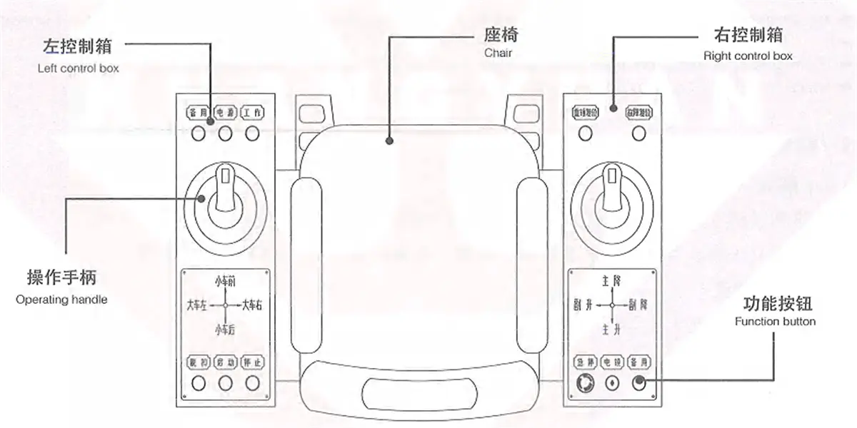
1.8 Operating equipment
1.8.1 Cab:
The cab arranged at the end of the bridge frame.
A linkage platform station is configured inside the cab and there is operating handle, function buttons, etc. to control motor’s starting, speed regulation, reversing and braking, and to finish the running operation of crane’s hoisting mechanism, trolley and bridge mechanisms. Please refer to Article 7.1 for specific descriptions in detail.
Figure 3-2 Arrangment Schematic Diagram of Linkage Station
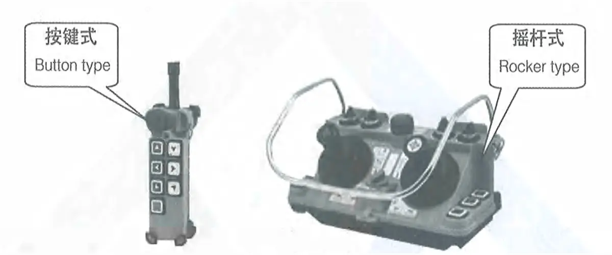
1.8.2 Remote control unit
Wireless remote control unit is configured with transmitter and receiver. The transmitter consists of encoding circuit and transmitting circuit, and the receiver consists of receiving circuit and decoding circuit. The transmitter will encode the button signal, modulate and convert it into electromagnetic wave and then send it out, the receiver will filter and amplify electromagnetic wave signal received, control the relay after decoding and identification, and drive electrical components and motor, so as to realize crane remote control. The receiver is mounted inside the stochastic control box. Operation personnel will carry the transmitter, can move freely and select the best safe visual position to carry out related operations.
According to different usage functions, remote control unit is divided into single (double)-speed button type and remote rocker type.
Figure 3-3 Remote Control Unit
1.8.3 Multipoint control
When cabin + remote control unit multipoint control mode is adopted, interlocking function is configured to ensure that only one control mode is effective within any given time. Each control point is configured with an emergency switch.
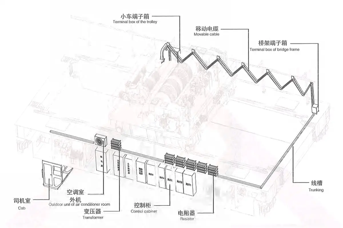
1.9 Electrical devices Arrangement
Electrical devices of the ladle crane (casting crane) are mainly arranged in the walking board, trolley, cab, end beam, electrical room, etc.
Figure 3-4 Electrical Arrangement Diagram
Maintenance hanging cage is mounted on the ladle crane (casting crane) bridge near the end of whole crane power feeding (it will not be configured when the cab and sliding wire in the same side), and the conductive frame is mounted at the same time for mounting the sliding wire collector. When the collector needs repair, after power off the sliding wire, maintenance personnel can enter into the maintenance hanging cage to carry out repair.
Power distribution protection cabinet (panel), drive control cabinet (panel), resistor, transformer and other relevant devices are generally mounted on the walking board (in case wide beam bridge frame is employed, except the resistor will be placed on the main beam, others electric devices will be placed in electrical room inside the main beam). Steel pipe or trunking will be employed for the wiring among electrical devices.
Junction box is mounted on end beam for the connection between trolley movable cable and the cable on bridge frame. According to the connecting cable type, can be divided into two categories, namely, round cable and flat cable.
Ladle crane (casting crane) operating equipment and signal devices are mounted inside the cab, including linkage control console, alarm device or electric bel for traveling alarm. lighting switch, lifting weight limiter display screen, etc. Conductor connection inside and outside the cab is completed through terminal board which inside cab’s back part of the closet.
Please refer to electric device layout provided with the equipment specifically.
Ladle crane (casting crane) electric drawing adopts mechanical code to show electric device of each mechanism. Common mechanism codes are as shown in Table 3-1.
Table 3-1 Common Mechanism Code
Mechanism code
Mechanism name
Mechanism code
Mechanism name
=01
Power distribution protection
=06
Auxiliary hoisting mechanism
=02
Lighting signal
=07
Sub-auxiliary hoisting mechanism
=03
Warming and cooling
=08
Main trolley travelling mechanism
=04
Remote control mechanism
=09
Auxiliary trolley travelling mechanism
=05
Main hoisting mechanism
=10
Crane travelling mechanism
Electric drawing of the crane adopts position code to show position relations of electric devices. Common position codes
are as shown in Table 3-2
Table 3-2 Position Code
Position code
Position name
Position code
Position name
+40
Cab
+52
Rear lower balancing beam and trolley
+41
Transmission side or cab right side main beam walking board
+60
Main trolley
+42
Conductive side or cab left side main beam walking board
+62
Auxiliary trolley
+43
Transmission side main beam walking board
+63
Lifting appliance
+44
Conductive side main beam walking board
+65
Sub-auxiliary trolley
+45
Bridge frame General term
+70
Fixed electric room
+48
Conductive maintenance platform
+71
Main beam electric room on transmission side
+49
Front end beam
+72
Main beam electric room on conductive side
+50
Rear end beam
+77
Movable electric room
+51
Front lower balancing beam and trolley
1.11 Electrical protection system
According to different demands, the ladle crane (casting crane) is configured with the following electrical protection functions
Motor protection.
According to motor and its control mode, the motor is configured with one of such protection functions: overcurrent protection, built-in heat sensor protection and thermal overload protection.
Zero position protection.
When the main power contactor is powered on again, it can be actuated only by toggling the operating handle back to zero position and pressing the button “start” again, otherwise, relevant mechanisms can’t be operated.
No-voltage protection.
After crane’s power supply is disconnected, all electric devices that involve in safety and shall not be started automatically will be in power failure condition, preventing automatic starting after the power supply is recovered.
Overspeed protection
Main hoisting mechanism is configured with overspeed switch. When the motor speed exceeds 130% of the rated speed, main power contactor will release and the brake will be locked.
Overload protection
Hoisting mechanism is configured with overload limiter. When the load reaches 95% of the rated load, the instrument box will send out a prompt alarm signal. When it reaches 105% of the rated load, it will send out a prohibitive alarm signal and the hoisting mechanism can' t lift, only can lower.
Travel limit protection.
The hoisting mechanism is configured with two-class protections for the lifting. The first-class protection will disconnect the mechanism’s main contractor, while the second-class will disconnect the main power contactor. The travelling mechanism is configured with left and right limit switch.
Ground protection.
Metal structure of the crane shall be connected reliably with supply line ground wire. Any hinge joint, fastening connection and wheel rolling contact shall not replace the required conductor connection. The cab and ladle crane ground point shall employ double ground wire connection.
Metal housing, electric metallic tubing and thunking of crane’s all electric devices shall be grounded reliably.
Gate open-closing interlock protection
Ladle crane (casting crane)’s each access door and cab entrance are configured with door opening/closing protection. When the door is opened, it will disconnect main power contactor and all mechanisms of the crane can’ t be operated.
Other protection.
The linkage station is configured with incoming line indicator light and the protection cabinet is configured with main contactor opening/closing status indicator light internally.
1.12 Routine control system
1.12.1 Routine control system is to connect with multi-step external resistance in motor rotor circuit. The master controller will give corresponding command to cut off motor’s three-phase resistor step by step through the contactor relay, time relay and other elements in control panel, so as to realize motor’s starting, speed control, reversing and braking.
1.12.1The master controller and control panel will cooperate to form a complete control system for controlling the motor’s starting, speed control, rotating direction change and braking. It is applicable to the following conditions:
1) Motor power is large, but the cam controller doesn’t have sufficient capacity
2) Operation frequency is high and power-on times per hour exceed 600 times.
3) The crane has heavy tasks and electrical devices shall have relatively high service life.
4) The crane has many mechanisms and it is required to reduce the driver’ s labor strength.
5) It is required to have good speed control and inching performances during crane operation
1.12.2 Main hoisting driving unit
QR2S-lI control panel is used for ladle crane (casting crane)’s main hoisting mechanism and can realize the starting, speed control, braking and motor reversing by cooperating with LK18-10/ master controller, and has short-circuit, overload, limit position and no-Voltage protection functions.
[Working principle]
Circuit breaker Q11S, reversing contactor 1K1S & 1K2S and 2K1S & 2K2S, overcurrent relays F21S-F22S andF23S-F24S are connected in motor stator circuit. Hydraulic brake is connected with AC contactors 1K7S & 2K7S. There is second-level reversely connected resistance, third-level accelerating resistance and first-level softening resistance in rotor circuit (motor power is no more than 90kW. In case the motor power is no less than 110kw, there will be fourth-level accelerating resistance and first-level softening resistance). The master controller has three gears respectively in lifting and lowering.
The first level and second level of the resistor can be cut off manually, while the third level, fourth level and fifth level will be cut off automatically through the control of time relay. Lowering 1st gear and 2nd gear of master controller refer to plug braking and can realize load lowering at a low speed, and the 3rd gear refers to regenerative braking and can realize quick lowering of the load.
When zero-voltage relay K00S is connected, two K00S auxiliary contacts will be connected to make the control circuit power on. At this time, time relay K02S will be connected, auxiliary contact K02S will be closed and AC contactor K44S will also be closed to make preparations for the AC contactor K43S connection. Besides, K44 will be closed and all reversely connected resistances of the rotor will be cut off.
When the lifting 1st gear, lifting AC contactor K1 can be connected only when rotor contactors K40S, K41S, K42S and K43S form fusion welding inspection link and are closed normally. NO contact K1S will be closed and AC contactor K7 will be connected to make its hydraulic brake started and start to lift. At the same time, K07S AC contactor will be closed and NC contact will be self-locked.
When the lifting 2nd gear, rotor AC contactor k43S will be closed, and the second-level reversely connected resistance will be cut off. Time relay K03S connected with k43 in parallel will be connected, its NO contact will realize time closing to make preparations for cutting off the first-level accelerating resistance.
when the lifting 3rd gear, since auxiliary contact of time relay K03S is connected with time delay, AC contactor K42 will be connected and the first-level accelerating resistance will be cut off. The motor will be accelerated for lifting. Time relay K04S connected with K42 in parallel will be connected, its NO contact will realize time closing, AC contaclorK41 will be connected, second-level accelerating resistance will be cut off, and the motor will be accelerated for lifting. Time relay K05S connected with K41 in parallel will be connected, its NO contact will realize time closing, third-level accelerating resistance will be cut off, and the motor will be accelerated for lifting again.
Lowering 1st gear refers to plug braking gear. Lifting AC contactor K1 can be connected only when rotor contactorsK40S, K41S, K42S and K43S form fusion welding inspection link and are closed normally. NO contact of K1 will be closed and AC contactor K7 will be connected to make its hydraulic brake started. ln addition, AC contactor K44S has been closed and first-level reversely connected resistance will be cut off. This gear is applicable to the lowering of heavy load. Lowering 2nd gear refers to plug braking gear. At this time, AC contactor K44S will be disconnected, the motor will be connected with maximum resistance to make the load lower at a ow speed. This gear is applicable to the lowering of light load.
Lowering 3rd gear refers to regenerative braking gear. At this time, AC contactors 1K1S & 1K2S will be disconnected AC contactors 1K2S & 2K2S will be closed, rotor AC contactor K43S will be closed, and second-level reversely connected resistance will be cut off. At the same time. time relay k03 connected with K43S in parallel will be connected. its NO contact will realize time closing, AC contactor K42S will be connected, and first-level accelerating resistance will be cut off. Time relay K04S connected with K42 in parallel will be connected, its NO contact will realize time closing. AC contactor K41S will be connected and second-level accelerating resistance will be cut off. Time delay K05S connected with K41S in parallel will be connected, its NO contact will realize time closing and third-level accelerating resistance will be cut off to make the motor accelerated for lowering step by step. Lt can realize quick lowering of light load.
When the handle of master controller is pushed back to zero gear from a certain position, K7S will be disconnected immediately. Since NC contact of K01S realizes time breaking, K07 and k1 will also realize time breaking, so that the brake can be powered off prior to the main motor to prevent hook gliding during the parking.
When NC contacts of K1S & K2S and NO contact K7S are connected serially in coil circuit of time relay K01S for corresponding control, it can play the following roles: when both K1S and K2S are not connected and K7S is connected abnormally, K01S will also be connected to make k07S coil power off and k7S will be disconnected to prevent free lowering of heavy object. When motor NC contacts K43S, K42S,K41S and k40S are connected in series in coil circuits of K1 sand k2S to form fusion we ding inspection link, only when above contactors are disconnected normally can forward or reverse contactor K1S or K2S be allowed to be connected.
Model of the resistor matching with electric control equipment is RF5-. In case the user discovers that lowering happens to lifting 1st gear during the full load, but the lowering is not expected by the user, it’s able to change the wiring of resist tap, so as to change the characteristics of lifting 1st gear and lowering 1st gear.
Setting value of time-delay relay: K01S : 0.6S,K02S : 0.7S, K03S: 04S, K4S: 0.6S, K05S: 0.3K06S: 0.15SSetting value of overcurrent relay is 2.5times of the rated current of the motor.K08S will provide ant-adhesion protection for forward/reverse contactor. When adhesion phenomenon happens, power on time-delay relay KO8S for time-delay operation and disconnect the master contactor to prevent any accident arising from contactor adhesion.
“-SA” is arranged on the linkage station, which ls the control changeover switch of two motors of the main hoisting mechanism. When two motors run simultaneously, the changeover switch will be in middle gear. When it is required to adjust the rope length, it’s able to select the motor through changeover switch to carry out corresponding adjustment.
Figure 3-5. Schematic Diagram of QR2S-Il Hoisting Control Panel
[Operation precautions]
During the operation, in case the heavy object can’t be lifted in lifting 1st gear, it’s able to push the handle to the 2nd gear because starting torque of lifting 1st gear is about 0.7Me and starting torque of 2nd gear is about 1.5Me.
Various lifting gears refer to the rotor resistance starting. The 1st gear and 2nd gear are used for starting transitional gear and short-distance adjusting movement, and the 3rd gear is high-speed operation gear. As to the operations in lowering direction, it is able to select the gear correctly according to the weight of heavy object and the requirements on lowering speed and lowering distance. When it’s less than half load, lowering 1st gear may have lifting phenomenon falsely. At this time. it’ s required to push the handle to lowering 2nd gear. In a similar way, in case lifting happens falsely in lowering 2nd gear, the handle shall be pushed to lowering 3rd gear.
The handle of master controller can be pushed to any lifting gear directly from lowering 3rd gear to realize automatic time delayed acceleration for lifting after the deceleration by plug braking.
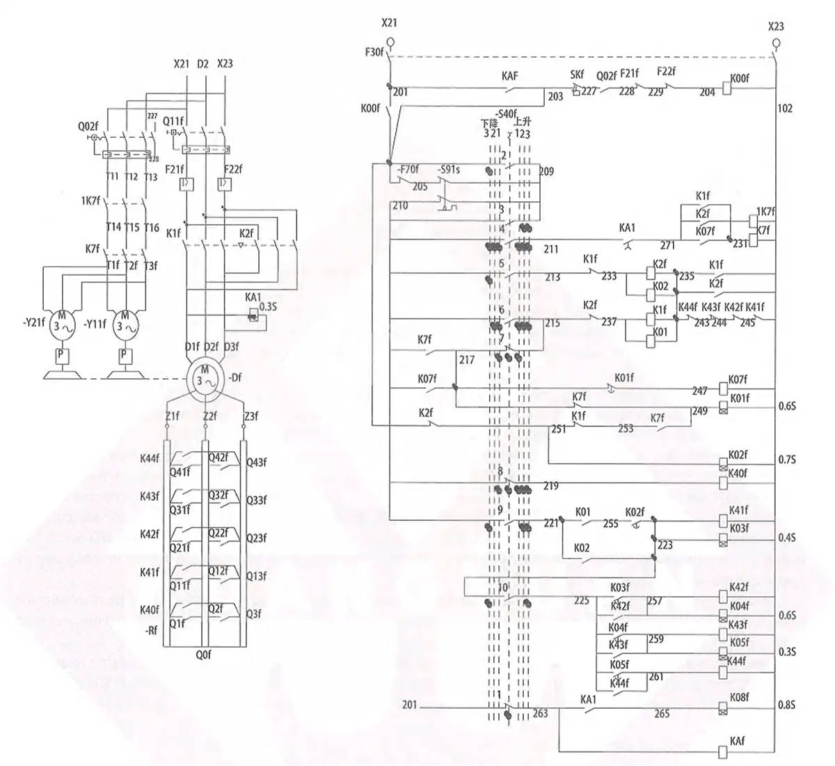
1.12.3 Auxiliary hoisting driving unit
QR2S-Il control panel is used for ladle crane (casting crane) auxiliary hoisting mechanism and can realize the starting, speed control, braking and reversing of the motor by cooperating with LK18-10/ master controller and has short-circuit, overload, limit, zero position and no-voltage protection functions.
[Working principle]
Circuit breaker Q11F, reversing contactors K1F & K2F and overcurrent relays F21F & F22F are connected in stator circuit of the motor. Hydraulic brake is connected with AC contactor 1k7F. There is second-level reversely connected resistance third-level accelerating resistance and first-level softening resistance in rotor circuit (in case the motor power is no less than110kW, there will be fourth-level accelerating resistance and first-level softening resistance). The master controller has three gears respectively in lifting and lowering.
The first level and second level of the resistor can be cut off manually, while the third level, fourth level and fifth level will be cut off automatically through the control of time relay. Lowering 1st gear and 2nd gear of master controller refer to plug braking and can realize load lowering at a low speed, and the 3rd gear refers to regenerative braking and can realize quick lowering of the load.
When zero-voltage relay K00F is connected, two auxiliary contacts of K00F will be connected to make the control circuit power on. At this lime. time relay K02F will be connected. Auxiliary contact of K02F will be closed and AC contactor K44F will also be closed to make preparations for the connection of AC contactor K43F. Besides, K44F will be closed and all reversely connected resistances of the rotor will be cut off. During the lifting 1st gear.
Lifting AC contactor K1 can be connected only when rotor contactors K40F, K41F, K42F and K43F form fusion welding inspection link and are closed normally. NO contact of K1F will be closed and AC contactor K7 will be connected to make its hydraulic brake started and start to lift. At the same tie, K07F AC contactor will be closed and NC contact will be self-locked.
During the lifting 2nd gear, rotor AC contactor K43F will be closed, the second-level reversely connected resistance will be cut off. Time relay ko3 connected with k43 in parallel will be connected. Its NO contact will realize time closing to make preparations for cutting off the first-level accelerating resistance.
During the lifting 3rd gear, since auxiliary contact of time relay K03F is connected with time delay, AC contactor K42 will be connected and the first-level accelerating resistance will be cut off. The motor will be accelerated for lifting.
Time relay K04F connected with K42 in parallel will be connected, its NO contact will realize time closing, AC contactorK41 will be connected, second-level accelerating resistance will be cut off, and the motor will be accelerated for lifting.
Time relay K05F connected with K41 in parallel will be connected. its NO contact will realize time closing, third-level accelerating resistance will be cut off, and the motor will be accelerated for lifting again.
Lowering 1st gear refers to plug braking gear. Lifting AC contactor k1 can be connected only when rotor coniactorsK40F, K41F, K42F and K43F form fusion welding inspection link and are closed normally, NO contact of K1 will be closed and AC contactor K7 will be connected to make its hydraulic brake started. In addition, AC contactor K44F has been closed and first-level reversely connected resistance will be cut off. It will start to lower. This gear is applicable to the lowering of heavy load.
Lowering 2nd gear refers to plug braking gear. At this time, AC contactor K44S will be disconnected, the motor will be connected with maximum resistance to make the load lower at a low speed. This gear is applicable to the lowering of light load.
Lowering 3rd gear refers to regenerative braking gear. At this time, AC contactor K1 will be disconnected, AC contactor K2F will be closed, rotor AC contactor K43F will be closed, and second-level reversely connected resistance will be cut off. At the same time. time relay K0F connected with k43F in parallel will be connected, its NO contact will realize time closing. AC contactor K42F will be connected, and first-level accelerating resistance will be cut off. Time relay K04F connected with K42 in parallel will be connected, its NO contact will realize time closing. AC contactor K41S will be connected and second-level accelerating resistance will be cut off. Time delay K05s connected with K41F in parallel will be connected, its NO contact will realize time closing and third-level accelerating resistance will be cut off to make the motor accelerated for lowering step by step. It can realize quick lowering of light load.
When the handle of master controller is pushed back to zero gear from a certain position, K7S will be disconnected immediately. Since NC contact of K01F realizes time breaking, K07 and K1 will also realize time breaking, so that the brake can be powered off prior to the main motor to prevent hook gliding during the parking.
When NC contacts of K1F and K2F and NO contact of K7S are connected in series in coil circuit of time relay K01for corresponding control, it can play the following role: when both K1S and K2F are not connected and K7S is connected normally, K01F will also be connected to make k07F coil power off and K7S will be disconnected to prevent free lowering of heavy object.
When NC contacts of rotor contactors K43F, K42F, K41F and K40F are connected in series in coil circuits of K1F and K2F to form fusion welding inspection link, only when above contactors are disconnected normally can forward or reverse contactor K1F or K2F be allowed to be connected.
Model of the resistor matching with electric control equipment is RF5-. In case the user discovers that lowering happens to lifting 1st gear during the full load, but the lowering isn’t expected by the user, it’s able to change the wiring of resistor tap, so as to change the characteristics of lifting 1st gear and lowering 1st gear.
Setting value of time-delay relay: K01F : 0.6S,KO2F: 0.7S, K03F : 04S,K04F : 0.6S,K05F: 0.3S,K06F: 0.15S Setting value of overcurrent relay is 2.5 times of the rated current of the motor.
K08F will provide anti-adhesion protection for forward/reverse contactor. When adhesion phenomenon happens, power on time-delay relay K08F for time-delay operation and disconnect the master contactor to prevent any accident arising from contactor adhesion.
Figure 3-6 Schematic Diagram of QR2S Hoisting Control Panel
[Operation precautions]
During the operation, in case the heavy object can’ t be lifted in lifting 1st gear, it’s able to push the handle to the gear because starting torque of lifting 1st gear is about 0.7Me and starting torque of 2nd gear is about 1.5Me.
Various lifting gears refer to the rotor resistance starting. The 1st gear and 2nd gear are used for starting transitional gear and short-distance adjusting movement, and the 3rd gear is high-speed operation gear.
As to the operations in lowering direction, it’s able to select the gear correctly according to the weight of heavy object and the requirements on lowering speed and lowering distance. When it’s less than half load, lowering 1st gear may have lifting phenomenon falsely. At this time, it’s required to push the handle to lowering 2nd gear. In a similar way, in case lifting happens falsely in lowering 2nd gear, the handle shall be pushed to lowering 3rd gear.
The handle of master controller can be pushed to any lifting gear directly from lowering 3rd gear to realize automatic time delayed acceleration for lifting after the deceleration by plug braking.
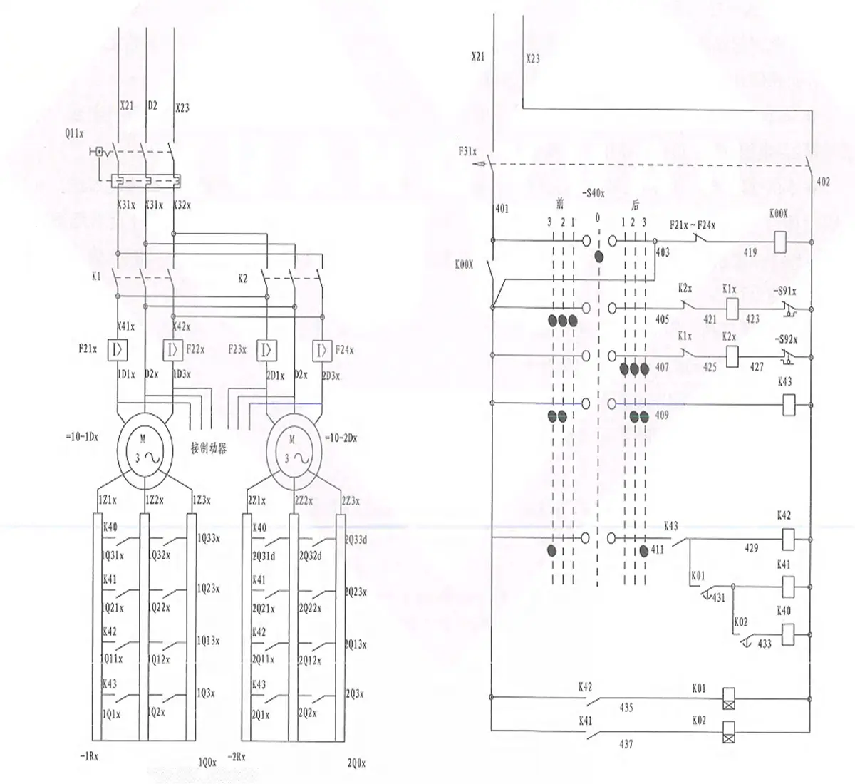
1.12.4 Trolley travelling driving unit
QR1Y series control panel is developed by design modification on the basis of the original product (PQY1-4) designed uniformly in 1974. QR1Y is reversible symmetric circuit and can control one, two or four motors. An introduction will be given with the control of 2 motors as an example herein.
Corresponding gear number of ladle crane (casting crane) master controller of QR1Y series control panel is 3-0-3, starting resistance includes four levels (excluding common cascade level). The first level and second level can be cut off manually, while the third level and fourth level will be cut off by the time relay control. The brake and motor will connect and disconnect with power supply simultaneously.
[Working principle]
Close the main circuit breaker Q11X and close the control circuit breaker F31X, S40-1 will be closed, K00 will be pulled in, NO contact of K00 will be closed and the control circuit will be powered on.
Rightward 1st gear: (S40-1 is disconnected, but due to self-insurance wire, K00 still keeps put-in state). S40-2 will be closed and K1 will be pulled in (the motor will be started. At this time, the starting torque will be 0.35Me, which is mainly used to eliminate gear clearance at a low speed. Then the motor will be started at a low speed. In case it feels that the starting torque is too low. It’s able to realize Q01-Q0 short circuit. In this way, the starting torque will be 0.5Me).
Rightward 2nd gear: S40-4 will be closed and K43 will be pulled in (resistances Q1, Q2 and Q3 will be cut off). The motor will be accelerated and K43-1 will be closed (making preparations for cutting of 2nd-gear resistances Q11, Q12 andQ13).
Rightward 3rd gear: S40-5 & S40-6 will be closed, K42 will be pulled in (resistances Q11, Q12 and Q13 will be cut off) and the motor will be accelerated continuously. K42-1 will be closed, K01 will be pulled in (with time delay of 3s), K01-1 will be closed, K41 will be pulled in (resistances Q21, 022 and Q23 will be cut of) and the motor will be accelerated continuously. K41-1 will be closed, K02 will be pulled in (with time delay of 1.5s), K02-1 will be closed, K40 will be pulled in (resistances Q31, Q32 and Q33 will be cut off) and the motor will be accelerated to run at a high speed.
Back to the 2nd gear: S40-5 & S40-6 will be disconnected, K40, K41 & K42 will be disconnected (resistances Q11Q12,Q13,Q21,Q22,Q23,Q31, Q32 and Q33 will be connected again).
Back to the 1st gear: S40-4 will be disconnected and K43 will be disconnected (resistances Q1, Q2 and Q3 will be connected again).
Back to zero gear: S40-2 will be disconnected, K1 will be disconnected. and the motor will be disconnected with power supply and realize braking & parking.
Leftward gears are similar to rightward gears.
Setting value of time-delay relay: K01: 3S, K02: 1.5S. Setting value of overcurrent relay is 2.5 times of the rated current of the motor.
Figure 3-7 Schematic Diagram of QR1Y Operation Control Panel
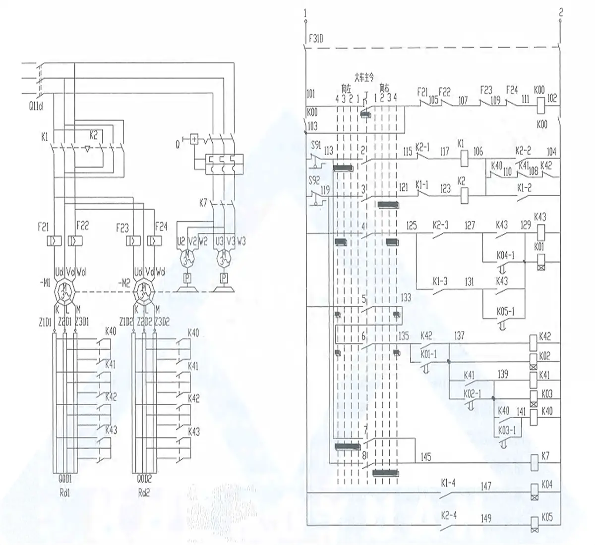
1.12.5 Crane bridge travelling driving unit
QR3Y series control panel aims to manipulate the control circuit of wound rotor type motor of ladle crane (casting crane) travelling mechanism through master controller. It can realize the starting, speed control, braking and reversing of the motor, and has short-circuit, overload, limit, zero position and no-voltage protections. Besides, it can control one, two or four motors simultaneously. Next an introduction will be given with the control of 2 motors as an example.
[Circuit characteristics]
Reversible symmetric circuit, open-loop control.
Gear number of mater controller is 4-0-4, including 8 circuits.
The starting torque of forward/reverse 2nd gear is about 0.5Me and the starting torque of 3rd gear is about 1.25Me.
Starting resistance level, three-phase resistor: four levels (100kW). The first-level starting resistance will be cut off manually, while other resistances will be cut off automatically through the control of time-delay relay.
Forward/reverse 1st gear is gliding gear. At this time, the brake will be powered on, while the motor will not be powered on. When the handle is pushed to this gear during the operation, the mechanism will glide by virtue of inertia and be decelerated on the track. It’s required to push the handle back to zero position in an appropriate time to realize locking and Parking. In this way, it can not only reduce both mechanical shock during the parking and braking abrasion, but also improve the parking accuracy.
The 2nd gear and 3rd gear are starting gears, while the 4th gear is high-speed operation gear
The circuit allows to push the handle to any reverse gear during operation process and it will not result in excessive large current impact of the motor (the circuit can guarantee that the motor will connect with all resistances in series for deceleration by plug braking. and then realize reverse starting)
There is rotor contactor fusion welding inspection ink in the circuit. When contactor K40, K41 or K41 has fusion welding phenomenon, the motor can' t be started.
Reference setting value of each time relay:
K01:1.5S, K02 3S, K03:1.5S, K04:6S, K05:6S.
Setting value of over current relay is 25 times of the rated current of the motor.
[Working principle]
Circuit brake Q11D, reversing contactors K1 & K2 and overcurrent relays F21, F22, F23 & F24 are connected in the main circuit, and knife switch 2DK and contactor K7 are connected in brake circuit. There is fourth-level starting resistance and first-level softening resistance in rotor Circuit. The master controller has four gears respectively in forward and reverse directions. Since the travelling mechanism is inertia load, there are the same performance characteristics in forward and reverse directions of the circuit. During the debugging and fault inspection, it’s able to disconnect 1DK and close 2DK, and then operate the master controller to check if all contactors and relays work normally.
This circuit can realize four protections:
No-voltage protection: after the network voltage drops to a certain value, K00 will be released to control power failure of the circuit. so that the mechanism can stop working.
Overload or short circuit protection: in case overload or short circuit happens to the main circuit, corresponding over current relay will act. Its NC contact will be disconnected and k00 will be released to control power failure of the circuit, so that the mechanism can stop working.
Zero position protection: after K00 ls released due to any reason, it’ s required to pull the handle of master controller back to zero position and then K00 can be connected again to prevent the starling of the motor when the driver isn’t in corresponding operating post or in the condition that the resistance is cut off in motor rotor circuit
Limit protection: When the limiting rule runs into limit switch, NC contact of the limit switch will be disconnected, so that the contactor will be disconnected and the motor will brake and park.
Figure 3-8 Schematic Diagram of QR3Y Operation Control Panel
1.13 Variable frequency inverter speed control
Please refer to the attached product manual and drawing in detail.
1.14 Stator variable voltage and speed control
Please refer to the attached product manual and drawing in detail.
.WEBP)