1.6 Impact on Environment
No friendly impact on surroundings may be caused, if incorrect treatment happened during the installation, usage and maintenance. For details, please refer to the following table:
| Table 1-2 Impact on Environment |
| Item |
lmpact on Environment |
Preventative Measure |
| When installing, maintaining or disassembling |
A certain amount of solid waste will be generated during construction |
Disposal following local regulations |
| When lubricating oil leaks |
Cause soil and water pollution |
Check the leakage point and repair until no leakage is found |
| When replacing lubricating oil |
Pollute soil and water due to uncontrolled discharge |
Waste grease shall be collected in dedicated containers |
| When meshing points wear out severely |
Noise exceed the limits, influence the operator |
Calibrate, adjust or replace worn parts |
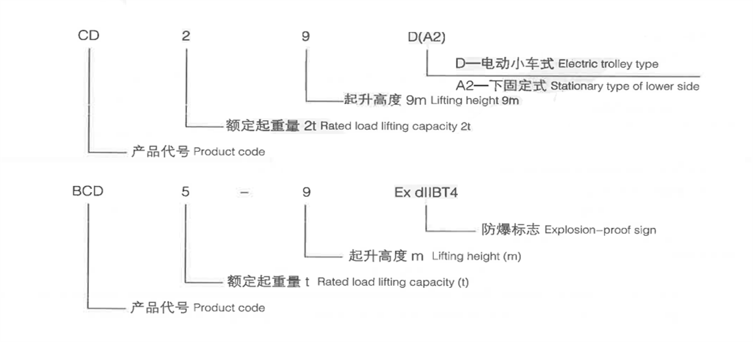
1.7 Representation Method of Type
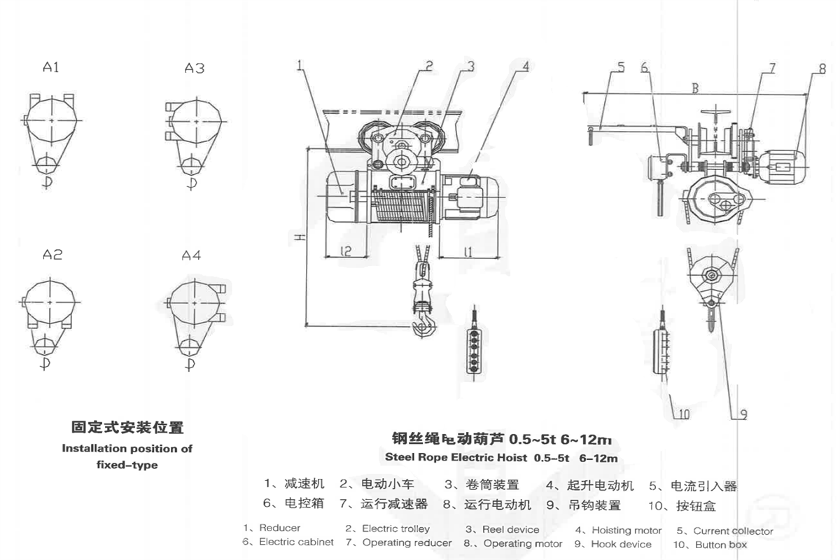
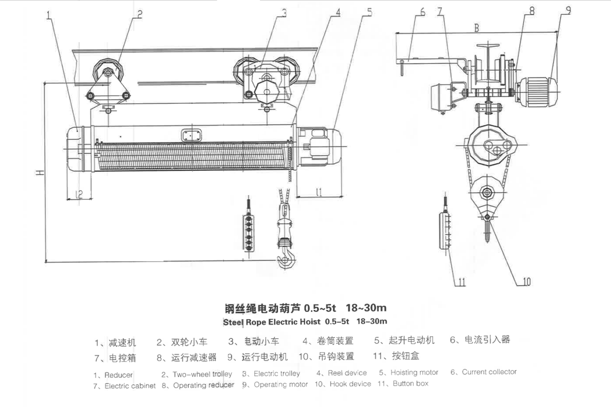
2. Structural Feature
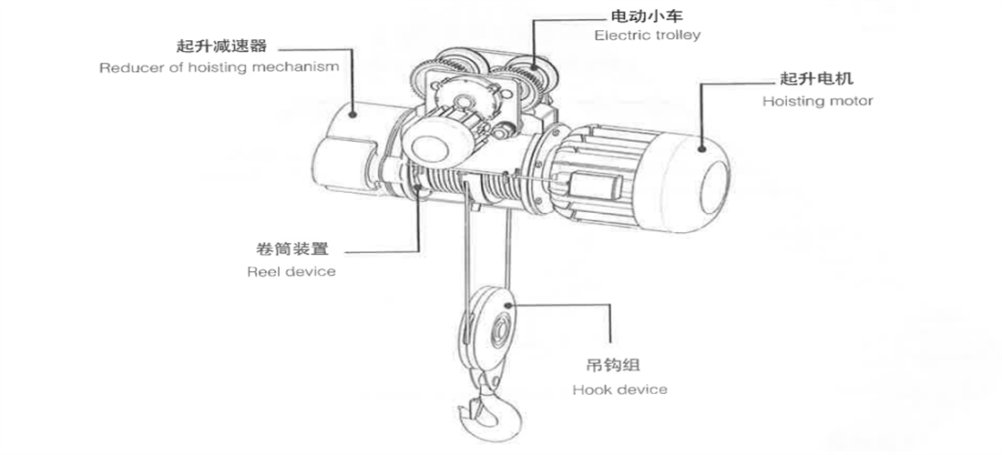
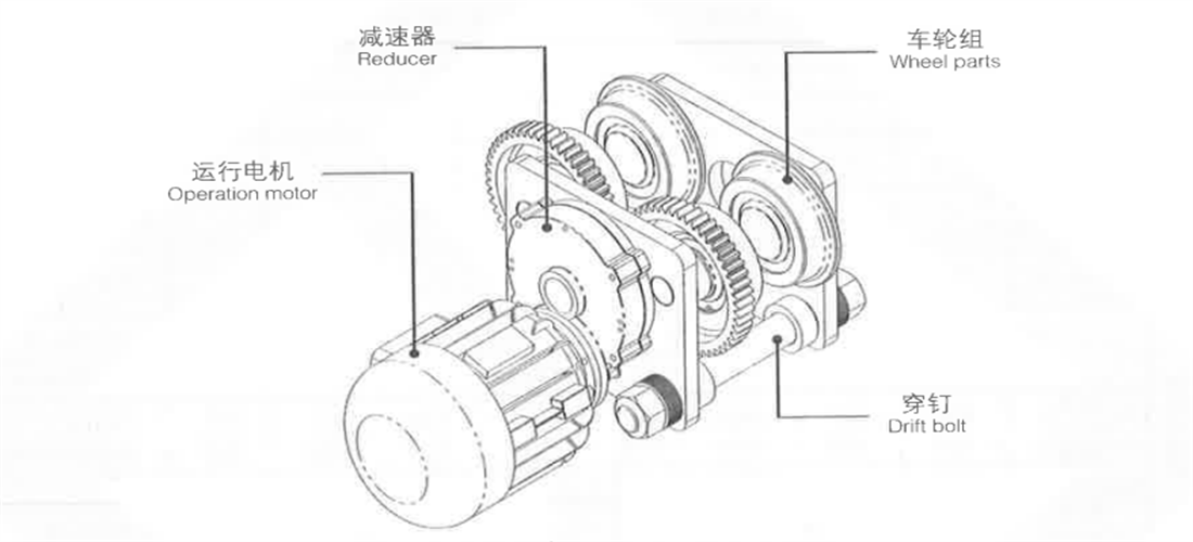
Monorail wire rope electric hoist is mainly composed of hoisting mechanism, electric trolley (stationary type with no this part) and electric appliance. The bracket part of following content is used for explosion-proof electric hoist.
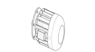
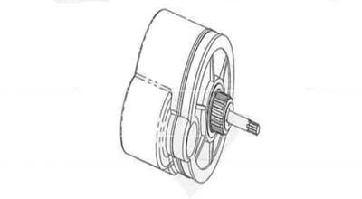
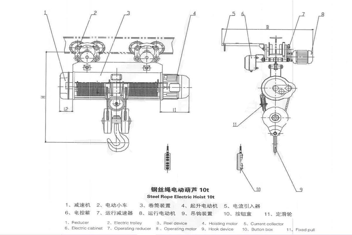
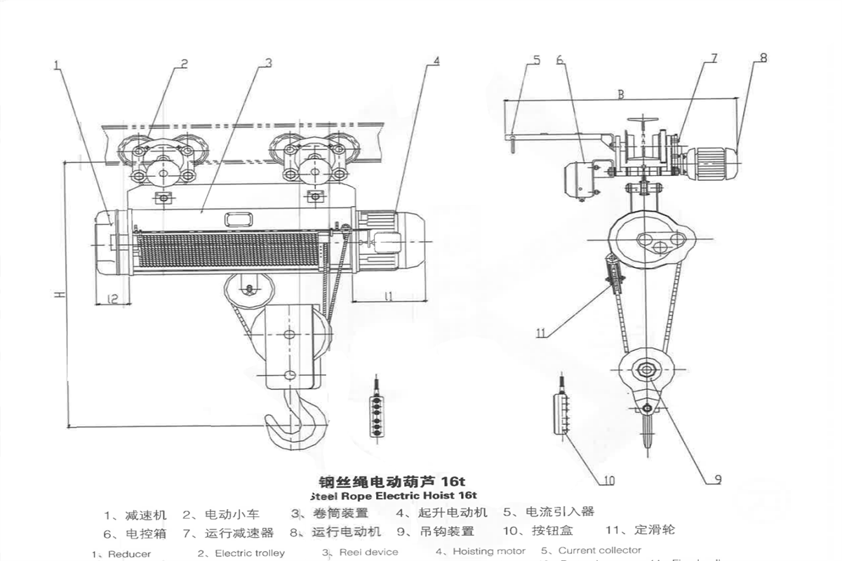
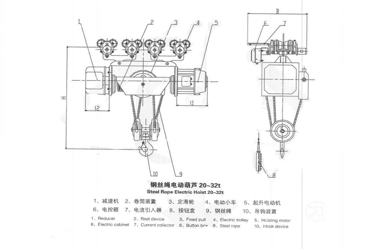
Fig. 2-1 monorail wire rope electric hoist outline drawing
2.1 Hoisting Mechanism
Hoisting mechanism consists of hoisting motor, reducer (gear box), reel device, hook block, electric trolley and electric control box. The hoisting motor, reducer, and reel device are arranged in series. Through shaft coupling, the lifting motor drives reel to rotate by reducer’s hollow shaft, let the wire rope on the reel drives the hook device moving upward and downward.
If the lifting height H=6m, use an elastic coupling to connect motor shaft and reducer’s input shaft;
If H ≥ 9m, add an intermediate shaft and rigid coupling.
If H ≥ 18m, equip with a supporting frame to intensify rigidity of intermediate shaft,thus keep rotation stable.
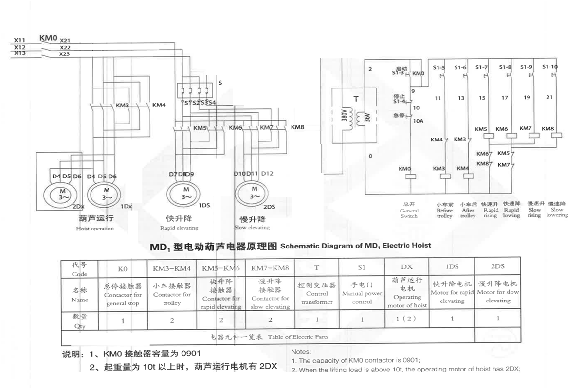
On the basis of high-speed driving, MD and BMD type hoisting mechanism add low speed actuating device composed of low-speed motor and reducer, and the ratio of high speed and low speed is 10:1. When high speed motor works, low speed actuating device doesn’t work, electric hoist lifts up and down in high speed. When low speed motor works, low speed actuating device drives conical rotor of main hoisting motor to rotate and electric hoist lifts up and down in low speed
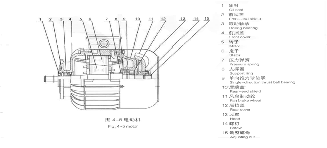
2.1.1 Motor
Hoisting motor uses (explosion-proof) squirrel cage conical brake motor and the maximum torque is the 2-3 times of full load torque to fit in direct starting of hoist’s interrupted operation electric hoist.
CD hoist is equipped with ZD1 single speed motor: MD hoist is equipped with ZDS type double speed motor (BCD hoist is equipped with BZD single speed motor; BMD hoist is equipped with BZDS double speed motor), the ratio of high speed and low speed is 10:1.
Fig.2-2 motor
2.1.2 Reducer
Reducer applies for helical gear three-level deceleration. Wheel gear and gear shaft are made by alloy steel and been heat treated. The shell is made of cast iron by strict assembling and in good seal.
Fig.2-3 reducer
2.1.3 Reel device
Reel device is the key part of monorail wire rope electric hoist, it connects with travelling mechanism through equalizing beam in the upper side, connects with lifting reducer and motor in two ends, and cooperates with hook rope at the lower side. The upper side in the front of shell is equipped with limit switch guide-rod device.
Drum is made of seamless steel tube and transfers power by spline; the drum shell is welded by steel plate. Rope guide is composed of rope guide nut, rope guide plate and connecting steel belt.
Rope guide is consisted of guiding nuts, guiding plate and connecting steel belt. Steel wire rope stretches out from long groove of rope guide plate. Guiding nut and drum block rope race meshes. Rope guide makes axial movement along with rotation of drum block to ensure wire rope neatly arranged on the drum block. When the hook rises to the extreme position, collision plate of rope guide collides stop block on the right, and pushes limit lever post to move right, so limit switch is triggered to cut power supply of motor. When the hook falls to rope guide plate, collision plate of rope guide collides stop block on the left and pushes limit lever post to move left so limit switch is triggered to cut power supply of motor thus ensure safe operation of electric hoist.
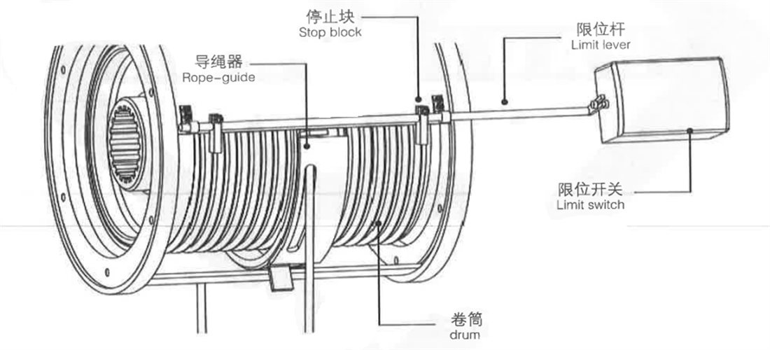
Fig.2-4 Reel device
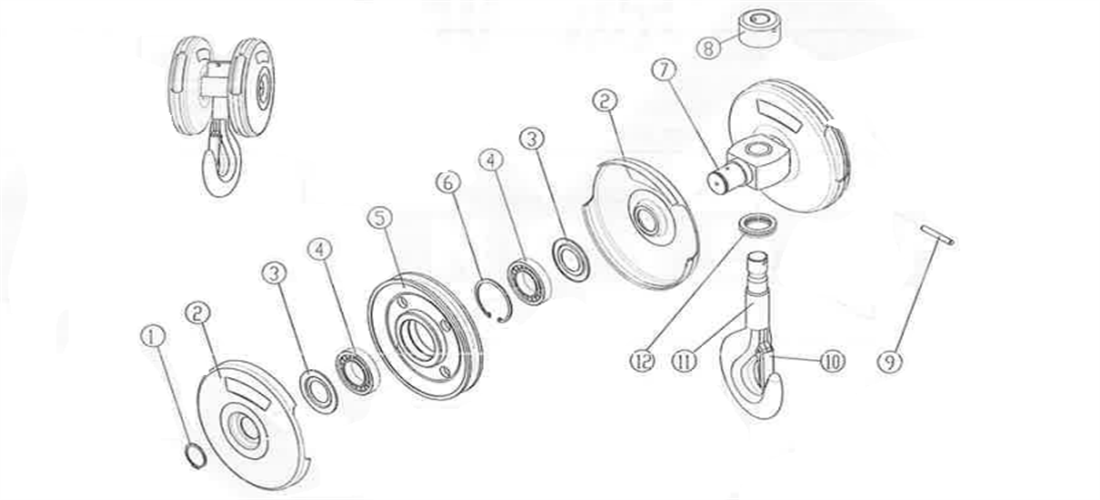
2.1.4 Hook Pulley Device
Hook is forged with #20 steels; Use thrust bearing to connect shell, through lifting hook beam, to make lifting hook rotate flexibly. Pulley is made of cast iron. Lifting hooks of 5t and under 5t are single pulley type, while lifting hooks of 10t and above are double pulley or multi-pulley. Mouth of hook is equipped with safety card.
Fig.2-5 Hook block with Single pulley
Fig.2-6 Hook block with double pulley
1-Retaining ring 2-Half cover of pulley 3-Dust cover 4-Bearing 5-Pulley 6-Retaining ring
7-Beam 8-Nut 9-Pin 10-Ciammp 11-Hook 12-Bearing
2.2 Electric trolley
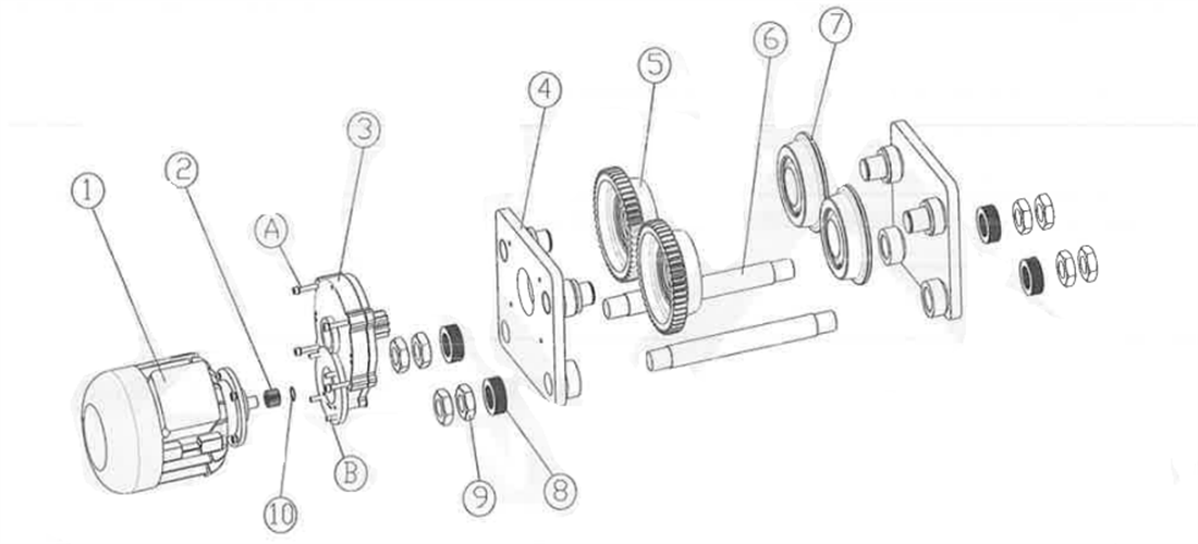
Electric trolley is composed of travelling motor, reducer (gear box) and wheel block. Travelling motor drives reducer through pinion on the end of axis to make gear rim driving wheel rotate. Reducer use spur gear second level deceleration, and gear is forged by superior alloy steel, and heat treated.
0.5-5t electric trolley is equipped with 4 travelling wheels when the lifting heights are 6m and 9m (including 0.5t-12m); When the lifting height ≥12m, a small frame plate with two traveling wheels is added. At the same, joint of electric trolley and reel cover is equipped with 2 added knuckle bearings.
10-20t monorail wire rope electric hoist is consisted of 2 electric trolleys, it is connected with drum cover by 2 knuckle bearings. In order to suit for different rail, adjusting washers are fitted with at the two ends of through bolt.
Fig.2-7 Electric Trolley
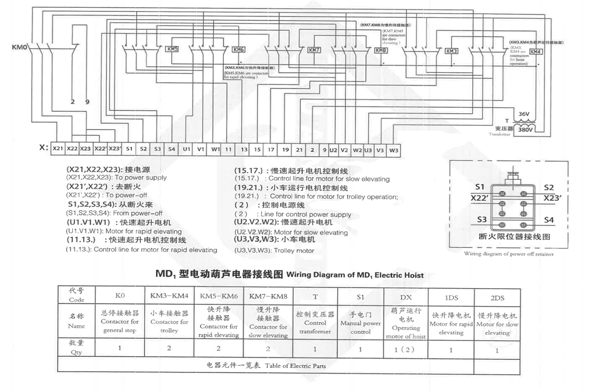
2.3 Electrical appliance
Electrical appliance consists of (explosion-proof type) electric cabinet, (explosion-proof type) travel switch, (explosion-proof type) handheld control button pendant and cable, it has the protecting functions of voltage loss, limit and overload.
Lifting and travelling of monorail wire rope electric hoist is controlled by handheld control button pendant or remote control. Rated voltage of button box is 36V. Press button correctly according to direction sign showing on the button box, control electric hoist’s action through relay’s actuation and break equipped in the electric cabinet
Travelling limit switch is divided into power off limiter and gravity limiter, to limit hook’s travelling motion.
The electric hoist adopts a soft cable to power supply.
The electric control box is installed on the passive side of the electric trolley.
2.4 Technical Features
| Technical Parameter |
| Lifting Capacity(T) |
0.5 |
1 |
3 |
5 |
10 |
20 |
32 |
| Lifting Height(M) |
3 |
6 |
9 |
6 |
12 |
30 |
6 |
12 |
30 |
6 |
12 |
30 |
9 |
12 |
30 |
9 |
12 |
30 |
12 |
20 |
24 |
| Lifting Speed(m/min) |
8/0.8 |
8/0.8 |
8/0.8 |
8/0.8 |
7/0.7 |
4.2/0.42 |
3/0.3 |
| Cross speed(m/min) |
20 |
20/30 |
20/30 |
20/30 |
20/30 |
21.5 |
26 |
| wire rope |
Dia(mm) |
3.6 |
4.8 |
13 |
15 |
15 |
19.5 |
26 |
| Structure |
6*19 |
6*37+1 |
6*37+1 |
6*37+1 |
6*37+1 |
6*37+1 |
6*37+1 |
| Traveling Track |
16-28b |
16-28b |
20a-32c |
25a-45c |
30T-45c |
40b-63c |
above 63c |
| Min Curvature Radius(m) |
1.5 |
1.5 |
2 |
4 |
2 |
2.5 |
4 |
2.5 |
3 |
6 |
3.5 |
4 |
9 |
3.5 |
4 |
|
|
| Lifting Motor |
power(kw) |
0.2/0.8 |
0.4/1.5 |
0.4/4.5 |
0.8/7.5 |
1.5/13 |
2.2/18.5 |
2.2/18.5 |
| Rotation speed (r/min) |
1380 |
1380 |
1380 |
1380 |
1380 |
1380 |
1380 |
| Current(A) |
0.72/2.4 |
12.5/4.3 |
1.25/11 |
2.4/18 |
4.3/30 |
42 |
43 |
| Cross Motor |
power(kw) |
0.2 |
0.2 |
0.4 |
0.8 |
0.8*2 |
0.8*4 |
0.8*4 |
| Rotation speed (r/min) |
1380 |
1380 |
1380 |
1380 |
1380 |
1380 |
1380 |
| Current(A) |
0.72 |
0.72 |
1.25 |
2.4 |
2.4 |
4.3 |
4.3 |
| Basic size |
L |
616 |
688 |
760 |
758 |
954 |
1542 |
915 |
1121 |
1738 |
1047 |
1257 |
1887 |
1602 |
1783 |
2869 |
1747 |
1942 |
2997 |
2127 |
2697 |
2982 |
| L1 |
274 |
346 |
418 |
345 |
541 |
1129 |
380 |
586 |
1204 |
415 |
625 |
1255 |
875 |
1056 |
2142 |
948 |
1143 |
2409 |
1270 |
1840 |
2125 |
| L2 |
125 |
158 |
229 |
267 |
301 |
330 |
396 |
| L3 |
318 |
390 |
462 |
401 |
597 |
1185 |
448 |
654 |
1272 |
485 |
695 |
1325 |
949 |
1130 |
2216 |
1053 |
1246 |
2301 |
1130 |
1700 |
1985 |
| L4 |
190 |
1961 |
264 |
320 |
376 |
670 |
600 |
| B |
884 |
884 |
930 |
1058 |
1058 |
548 |
743 |
2009 |
320 |
| H |
650 |
667 |
767 |
954 |
1058 |
1120 |
1283 |
1350 |
288-310 |
2500(1500) |
| D |
14.5 |
19 |
25 |
31 |
30 |
25 |
25 |
| Self weight |
Lifting single speed |
121 |
125 |
130 |
137 |
172 |
220 |
281 |
354 |
451 |
437 |
597 |
726 |
1048 |
1098 |
1411 |
2450 |
1927 |
2169 |
2950 |
3495 |
3700 |
| Lifting double speed |
138 |
142 |
147 |
164 |
199 |
247 |
311 |
384 |
481 |
530 |
654 |
783 |
1104 |
1154 |
1467 |
3. Safety Rules
3.1 Basic Principles
1) Before operating a monorail wire rope electric hoist, relevant operators should be sure to have carefully read the Operation Manual, which should be placed within their reach for reading at any time.
2) An electric hoist is a special device designed to hoist and transport loads, during which, risks may occur, Therefore the operator is required to read and understand all content in the instructions and GB 6067.1 Safety Rules for Lifting Appliances carefully.
3) Operation and maintenance personnel must receive adequate training before working on jobs.
3.2 Instructions to Users
The user must ensure that operation and maintenance personnel strictly comply with relevant provisions set forth by the national labor and security departments. The information below is very important for the safety of monorail wire rope electric hoists, also to its operation and maintenance personnel:
1)The user must confirm that the electric hoist has been inspected and tested by professional worker initial trial run is carried out or run-again after a big maintenance.
2)The user must be sure that the electric hoist is inspected and tested by professionals at least once a year.
3)The user must keep all the results and records during the inspection and test to the hoist.
4)The electric hoist must be operated by a specially assigned person, who must fully master the related knowledge to the installation, maintenance and operation instructions.
5)The user should be sure that no side pull in operation.
6)The user should ensure that the electric hoist will not hoist a load beyond its rated load lifting capacity.
7)When obvious defects are fond, the operator must stop the operation soon and inform relevant maintenance personnel.
8)There will be no loads hung on the electric hoist for a long time when it is not in use.
9)Nobody is allowed to stand beneath an electric hoist when it is lifting a load, and remote control or non-follow me control should be applied to keep a distance to heat source.
10)The special hoist should be used for lifting molten steel,
11)Lifting limit switch is not allowed to used as a motion switch repeatedly.
12)Only the main power source is power off, maintenance can carry out operation.
13)Hook collision is forbidden strictly.
14) When the explosion-proof electric hoist is running, pay attention to preventing and avoiding the generation of dangerous sparks that can ignite explosive hazardous mixtures.
15)To ensure safe use, Electric hoists should be used in accordance with work regulations. For explosion-proof hoists, they should not be used frequently, otherwise it will cause brake friction heating temperature to increase and exceed the allowable value specified in the national standard GB3638.1, causing danger. Remember for users!!!
3.3 Injury Risk
- 1)Incorrect operation
- 2)Insufficient maintenance and upkeep
- 3)Do not pay attention to observation, when lifting the hook to the upper limit position
- 4)Failure to carefully read the safety instructions provided in the manual, may cause injury or even death,
- 5)If the product is operated with improper intent by untrained or insufficiently trained personnel, it may cause personal injury
- 6)Wearing loose clothing, jewelry, etc. may be involved in hoist
- 7)Taking nicotine, alcohol, or drugs can have an impact on the reaction ability of operators
- 8)The operator of the monorail wire rope electric hoist did not maintain a safe distance from the lifting object
3.4 Illegal operation (not limited to the followings)
1)The loadings exceed the rated lifting capacity.
2)Side pulls when hoist loads
3)Lifting or transporting personnel
4)Frequent jogging
5)The steel wire rope has protrusions, broken strands, or other damages, not been replaced
6)Continue to use in case of abnormal situations or abnormal noise
7)Using the electric hoist limit switch to stop the vehicle
3.5 Before Operation
As required, the operator should inspect the electric hoist to motor, brake, steel rope, and safety device, and eliminate abnormalities if found.
3.6 During Operation
1)When lifting for the first time in each shift (or when the load reaches its maximum rated lifting capacity), the object should be lowered again 0.5 meters above the ground to check the brake performance, confirm reliability, and then proceed with normal operations.
2)The operator should closely monitor the direction of operation and whether there are any personnel or obstacles near it.
3)It is strictly prohibited to use one electric hoist to push another electric hoist.
4)It is strictly prohibited to pass over the human body when lifting objects.
5)When lifting, hands should not be held between the rope and the object.
6)When lifting objects, attention should be paid to observation to prevent them from hitting the top.
7)In case of any abnormality, press the button box [Manual emergency activation] button to disconnect the main power supply
8)The buffers at both ends of the I-beam track are only used as a limit for accidents and should not be collided frequently during normal operations.
9)If the wire rope is found to be loose or tangled, the rope guide should be removed first, then lowered to loosen the wire rope and rewound.
3.7 After Operation
1)Raise the hook to a position close to the highest point, stop the electric hoist at the designated position, and cut off the power supply.
2)Perform daily maintenance of monorail wire rope electric hoists
3)Do a good job in handover work
3.8 Emergency Stop
The button box is equipped with a mushroom shaped emergency stop button, during the operation process, if there is a discrepancy between the lifting or running actions and the instructions or other unexpected situations, the [Emergency Stop Button] can be pressed, disconnect the main power supply, stop all actions, and then investigate the cause.
1)Press the red EM button => Disconnect the main loop power supply of the electric hoist
2)Rotate the EM button clockwise => Release the button and start the machine
Fig. 3-1 EM Button
4. Installation and Commissioning
.png)
The installation and commissioning of electric hoists should be carried out by professional units with corresponding installation qualifications.4.1 Preparation before installation
4.1.1 open package inspection
1) Check whether the model, specifications, and quantity of the electric hoist and accessories meet the requirements of the technical documents according to the packing list, and whether there are complete random documents.
2) Check if the electric hoist is damaged during transportation. For explosion-proof hoists, when there are cracks or damages in the explosion-proof shell, the damaged parts must be returned to the manufacturer for replacement, and installation can only be carried out after meeting explosion-proof requirements. Users are not allowed to replace parts that do not meet explosion-proof requirements.
3) Check the steel wire rope for any damage, bending, twisting, or looseness that may affect its performance and safety.
4) The travelling trolley, current introducer, and hook device (excluding 10t) are generally disassembled and boxed with the main machine, and must be reassembled during installation.
5) Remove oil stains or rust preventive oil from the tread of the electric trolley.
4.1.2 Motor inspection
Check for axial movement of the tapered motor fan wheel. Method: Remove motor’s fan cover, use a lever to pry the fan brake wheel, with an average of 3 points on the outer end plane, and check whether the fan brake wheel and the cone surface of the rear end cover of the motor are rusted (as the brake ring inside the fan brake wheel is prone to moisture, it can bite and rust to the rear end cover of the motor, causing the motor to fail to start after being powered on, and the current will increase and burn out). If the rust is rusted, loosen the fan brake wheel and maintain an axial displacement of 1.5mm.
4.1.3 Electric control box inspection
Before powering on, use a multimeter to check if the electrical control box wiring is correct (to prevent loose wire ends during transportation). If the product has been shipped for more than 18 months (the date of shipment is the first four digits of the product number), please open the electronic control box to check for mold.
The above work has been checked and all items meet the requirements before proceeding to the next installation step.
4.1.4 Explosion proof performance inspection
Before installation, perform the following explosion-proof performance checks. If they do not meet the requirements, they are not allowed to be used.
1) The motor should be explosion-proof type;
2) The product label or tonnage label should be made of brass or stainless steel, and its thickness should not be less than 1mm
3) When the explosion-proof level is C or dust explosion-proof, the hook should take measures that can prevent dangerous sparks from collision or friction.
4) When the explosion-proof level is C or dust explosion-proof, the wheel tread and rim parts should be made of copper alloy, stainless steel, or other materials that will not ignite explosive gases or combustible dust mixtures due to impact or friction.
5) The roller of the explosion-proof electric hoist cable pulley and the collision wheel of the running limit switch should be made of bronze, brass, or engineering plastic with a surface charge of no more than 109Q. When the explosion-proof level is IC or dust explosion-proof, the traction wire of the cable pulley should be made of stainless wire rope.
6) The power supply of explosion-proof electric hoists should be introduced using flexible cables for conductivity
7) The rubber buffer should comply with the provisions of JB/T 8110.2, and the polyurethane buffer should comply with the provisions of JB/T 10833, and the surface resistance should not exceed 109Q.
8) Electrical equipment should meet the following requirements:
A. Having corresponding explosion-proof signs and explosion-proof certificates;
B. The explosion-proof category and temperature group of electrical equipment should meet the explosion-proof requirements of the workplace;
C. All fasteners are tightened, spring washers are not lost, and the connection between various components of the explosion-proof shell is appropriate;
D. All electrical equipment shall be free from defects such as deformation and cracks that affect explosion-proof performance, and the explosion-proof surface shall be free from bumps, scratches, and rust.
4.2 Installation
4.2.1 Electric trolley’s installation
1) The electric trolley is assembled together before leaving the factory, and only the number of washers needs to be adjusted during installation.
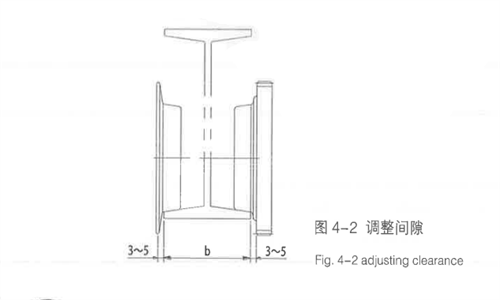
2) The I-steel rail for the travelling of the power supply hoist is selected and designed by the user according to the GB706 standard. Adjust with adjusting washers during installation to ensure that the gap between the wheel flange and the track is 3 ~ 5mm.
Figure 4-1 electric trolley
Figure 4-2 Adjusting clearance
| I beam rail model GB/T706 |
Rated lifting capacity(t) |
| 0.5~1 |
2~3 |
5~10 |
16~20 |
| 16 |
0 |
|
|
|
| 18 |
2 |
| 20a |
3 |
0 |
| 20b |
4 |
1 |
| 22a |
6 |
3 |
| 22b |
| 25a |
7 |
4 |
0 |
| 25b |
8 |
5 |
1 |
| 28a |
9 |
6 |
2 |
| 28b |
| 32a |
|
8 |
4 |
| 32b |
| 32c |
9 |
5 |
| 36a |
5 |
| 26b |
10 |
6 |
6 |
| 36c |
| 40a |
11 |
7 |
7 |
| 40b |
| 40c |
12 |
8 |
8 |
| 45a |
13 |
9 |
9 |
| 45b |
| 45c |
14 |
10 |
10 |
| 50a |
|
11 |
11 |
| 50b |
|
11 |
11 |
| 50c |
|
12 |
12 |
| 56a |
|
13 |
13 |
| 56b |
|
13 |
13 |
| 56c |
|
14 |
14 |
| 63a |
|
15 |
15 |
| 63b |
|
16 |
16 |
| 63c |
|
16 |
16 |
The quantities listed in the table are unilateral numbers to ensure a clearance of 3-5mm between the trolley wheel flange and the single side of the track.
4.2.2 Installation of electric control box
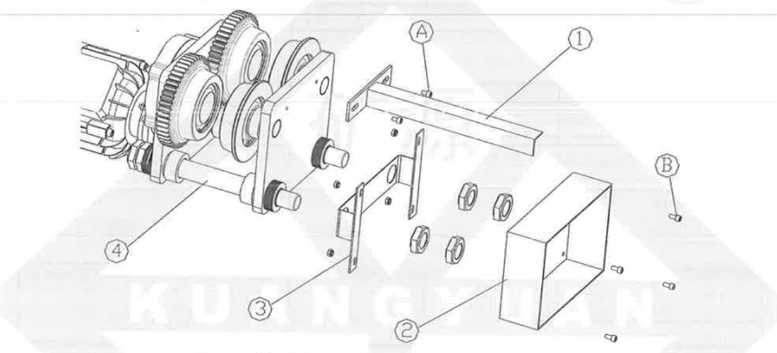
The electric control box and cable entry device are installed on the passive side of the electric trolley, fixed on the threaded bolt (considering the balance effect of the explosion-proof hoist electric control box, Installed on a dedicated bracket on the side of the lifting reducer.
Figure 4-3 Installation of electric control box
1-Cable introducer 2-Electric cabinet 3-Bracket 4-Electric trolley A, B-Fastening bolt
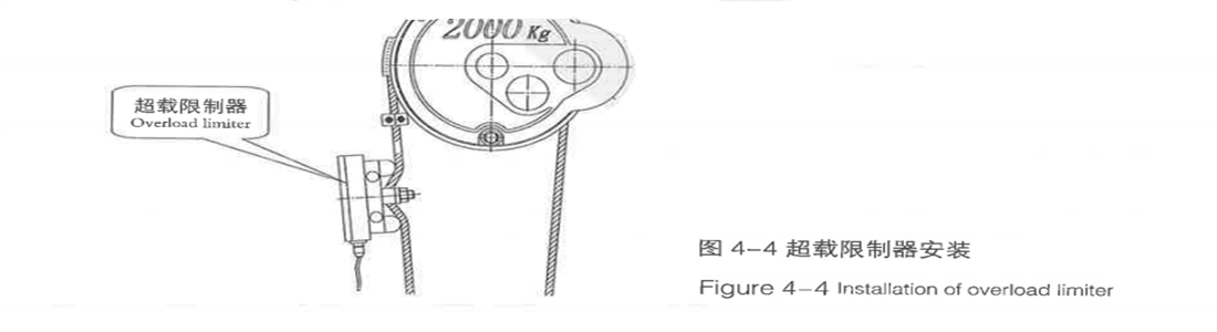
4.2.3 Installation of overload limiter
According to the relevant safety requirements of national special equipment, lifting equipment must be equipped with overload limiters, and their sensors must be installed at the fixed position of the electric hoist wire rope, for specific installation and debugging instructions, please refer to the special manual for the overload limiter.
Figure 4-4 Installation of overload limiter
4.2.4 Installation of gravity hammer limit switch
The gravity hammer limit switch is installed at the fixed end of the steel wire rope, the single wound rope type is installed at the fixed rope clamp, and the double wound rope type is installed at the fixed position of the overload limiter.
4.3 Commissioning
4.3.1 Motor adjustment
The axial displacement of the main shaft of the conical rotor motor is normally between 2-4mm, and the adjustment method is as follows:
- 1) To adjust the hoist motor of 5t and below, remove the tail cover, remove the four screws that fix the adjustment nut, use a wrench to rotate the adjustment nut clockwise for 1-2 turns, and then tighten the screw.
- 2) The adjustment method for the 10t~32t hoist motor is basically the same as above, except that the direction of rotation of the adjusting nut is opposite, that is, clockwise rotation increases the displacement, and counterclockwise rotation reduces the displacement.
Fig.4-5 motor
4.3.2 Adjustment of power off limiter
The adjustment of the power off limit device is achieved by adjusting the two collision blocks on the limit rod. The adjustment method is as follows:
1) Loosen the screws on the collision block and place it on both sides of the rope guide card. The card can freely push the collision block to move.
2) Start the motor and start to rise. The card plate pushes the upper limit collision block to move. When the upper edge of the hook pulley shell is 150mm~50mm away from the lower edge of the winding shell, stop rising and press the lowering button. When the rope guide moves back about 10mm, stop the machine. Move the upper limit collision block close to the card plate and tighten the screws.
3) The adjustment of the lower limit position is the same as above, but in the opposite direction, but it must be ensured that there are at least 2 coils of steel wire rope left on the drum when the hook is in the lowest position.
4) After the adjustment is completed, the no-load trial lifting can be carried out several times to verify whether the upper and lower limits meet the requirements
5 Test Run
Before using the monorail wire rope electric hoist, at least the inspections and debugging listed below must be carried out. In some cases, a more thorough inspection is required. The scope of inspection depends on the operating range and usage.
5.1 No load checks
5.1.1 Check the connection of electrical equipment
1) Check and ensure that the connections and wiring diagrams of the electrical devices are consistent, especially those that affect the safety and control of the electric hoist.
2) Check the wiring method of the wires to ensure that there are no obstacles caused by the staggered wiring structure during the operation of the electric hoist.
5.1.2 Inspection of button box
1) Check and ensure that the button box and suspended control wire are in good condition. Check and ensure that the button box is at the correct height.
2) Press the direction button on the button box, check and ensure that the direction indicated by the button matches the direction of the action.
3) If there are errors in all operating directions, correction can be made by changing the two phases’ sequences of the power supply. Change the phase sequence of the input power supply of the electric hoist.
4) Check the operation of the Manual fire alarm activation button.
If not necessary, do not press the Manual fire alarm activation button.5.1.3 Check for work noise
1) Determine whether there are installation errors based on the noise emitted during lifting and travelling.
2) If the lifting motor emits loud intermittent noise accompanied by severe vibration of the electric hoist, the problem may be caused by the power supply. Check and correct the phase sequence of the power supply.
3) If the operation produces loud noise and is accompanied by severe vibration, it is possible that the electric car has "gnawed the track" phenomenon. Installation of the incense inspection electric car on the track.
Do not use an electric hoist until the cause of undesired noise or vibration has been identified and eliminated5.1.4 Lifting limit switch inspection
Check the operation of the lifting limit switch inspection by lifting the hook to the upper and lower limit positions.
For safety reasons, before continuing the test, the hoisting limit switch must be adjusted
5.1.5 Operation inspection of hook pulley
Check and ensure that the pulley can freely rotate
5.1.6 Check on wire rope
1) Check and ensure that the wire rope is not damaged.
2) Check and ensure that the wire rope is wrapped around the drum and pulley in the correct way.
3) Check the fixation of the end of the wire rope.
The starting load of the new steel wire rope should be about 10% of the rated load. The load should be lifted to a total lifting height of 5-10%. If the hook rotates during the lifting process, it can be placed in the lowest position without load, opened the wedge sleeve at the end of the wire rope, and rotated until the hook is straight.
5.1.7 Check on electric trolley
1) Check the wheelbase of the trolley and adjust it correctly.
2) Check all installation screws for tightness.
3) Run at least 3-5 times throughout the entire rail length.
5.1.8 Check of braking operation
Check and ensure the hoisting brake can operate normally both in hoisting and lowering directions.
5.2 Check on Rated Lifting Capacity
5.2.1 Check on motor current
Check the motor current of each phase during the lifting operation under rated load. The current of all phases should be balanced and cannot exceed the rated current of the motor.
5.2.2 Check on electric trolley
1) Check and ensure smooth acceleration and braking.
2) Run at least 3-5 times throughout the entire length of the track. Remove any paint that has fallen off the track.
5.3 After Check
5.3.1 Clearing
Check and ensure all tools and extra material used in installation have cleared away from the electric hoist and rails.
5.3.2 User training
Be sure to let operators and executives of an electric hoist know the necessity of user training.
5.3.3 Delivery document
1) Check the documents has been delivered with the equipment. Ensure that the documents are correct in contents, and the reference data in the documents are consistent with contents shown the nameplate.
2) Write a test run record of the electric hoist and keep it with other documents of the electric hoist.
For explosion-proof monorail wire rope electric hoists, under no light conditions, there should be no sparks generated when observing the lifting and operating status of the electric hoist with normal human vision.
6. Usage and Operation
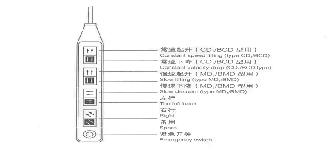
The lifting and travelling of the electric hoist is controlled by a button type electric hand door, which is suspended under the control box on the electric hoist through cables, and is equipped with start, stop, action buttons, Manual fire alarm activation and other devices.
When using the dual speed button, the operation should first transition from slow speed (first level) to fast speed (second level): When descending, the object should be lowered to a suitable height at high speed and then lowered to the designated position at low speed.
Figure 6-1 cable pendant
The appearance and wiring of the hand switch used in different control methods are different.
Use the following steps to activate the electric hoist in standby mode:
1)Rotate the emergency stop button clockwise to release, and the electric hoist will enter the working state;
2)Press the first level → slow speed (dual speed button);
3)Press all → Fast (dual speed button);
4)Release button→ Stop
Figure 6-2 Dual-speed button control
After operating the electric hoist, follow the following steps to return it to the standby state:
1)Move the electric hoist to the correct stop position and stop all electric hoist movements;
2)Press the [Emergency Stop Button] and the button is locked.
A. During each lifting, the button should be pressed to tighten the wire rope before lifting the load.
B. When the load is lifted from the ground level, it should be ensured that the load is balanced.
C. When the load avoids all obstacles, it can switch to fast continue (during dual speed control).
D. When lowering the load, it is necessary to quickly switch to low speed to control the speed reduction (during dual speed control).
7. Inspection and Maintenance
To ensure the reliability and lifespan of the monorail wire rope electric hoist, it is necessary to regularly inspect and maintain the electric hoist. The main vulnerable parts of this product include rope guides, sealing rings, brake rings, and running motor shaft end small gears.
7.1 Safety precautions
1) The inspection and maintenance site and adjacent areas shall be observed, and warning signs and safe working areas shall be set;
2) If encountering adverse weather conditions such as strong winds, thunderstorms, severe ice and snow, or heavy fog, outdoor inspections and maintenance should be postponed;
3) Electric hoists should be parked in an undisturbed area;
4) There should be warning signs indicating "inspection in progress" or "maintenance in progress", or the switch of the controller should be locked in the "off" position, and only designated personnel can identify and/or lock it;
5) If there is a load on the electric hoist, the load should be removed;
6) If the maintenance work above poses a danger to the lower part, warning signs and warning areas should be set up below;
7) Safe and reliable tools should be used;
8) Inspection or maintenance personnel should be equipped with personal protective devices (such as protective shoes, safety helmets, seat belts, or protective glasses);
9) Measures should be taken to prevent electric shock;
10) The safety performance of the tools used for repairing explosion-proof electric hoists should comply with the provisions of GB/T 10686. Inspection or maintenance personnel should be equipped with personal protective devices (such as protective shoes, safety helmets, safety belts, or protective glasses);
11) Measures to prevent electric shock should be taken;
12) During inspection, it is strictly prohibited to close or disconnect the power switch except for instructions given by designated personnel;
13) During the inspection, it is strictly prohibited to operate the electric hoist except for instructions given by designated personnel;
14) Before the load test, the attachments of the lifting appliance and the test load should be checked for defects;
15) Prohibit other personnel from entering hazardous areas unless authorized;
16) The inspection should be carried out by two or more inspectors together;
17) Adequate lighting should be provided during inspection or maintenance.
18) After maintenance work and before the electric hoist returns to normal operation, protective equipment should be reinstalled, safety protection devices should be restored, and calibrated.
19) Necessary firefighting measures should be taken during maintenance;
20) After the maintenance work is completed, the temporary facilities taken during maintenance should be removed and the site cleaned.
7.2 Daily inspection
Daily inspection items and requirements should be determined based on the specific characteristics of each equipment, and should not be lower than the provisions in Table 7-1.
7.3 Regular inspection
Determine regular inspection items, inspection requirements, and inspection cycles based on the working level, working environment, and usage status of each equipment, and should not be lower than the provisions in Table 7-1. For equipment used to lift hazardous materials such as molten metal, the inspection cycle should be appropriately shortened.
| Daily inspection and inspection items, content, methods and requirements |
| No. |
Item |
Inspection methods, content and requirements |
Processing methods |
Cycle |
|
| day |
month |
quarter |
year |
| 1 |
Technical documents |
Accompanying files |
Check that the accompanying drawings, user manual, and factory certificate are complete |
Improvement |
|
|
|
○ |
| 2 |
Inspection records |
Previous inspection records should be complete and free from any unresolved defects |
Improvement |
|
|
|
○ |
| 3 |
Maintain records |
Check that previous maintenance records are complete and have no unverified maintenance |
Improvement |
|
|
|
○ |
| 4 |
Other archives |
Check other files such as equipment installation, renovation, maintenance, registration, etc. |
Improvement |
|
|
|
○ |
| 5 |
Whole machine |
Operation environment |
Visually inspect the operating environment of the equipment to ensure that there are no factors affecting the safety of the operation |
Handle according to the enterprise management system and operating procedures |
○ |
○ |
○ |
○ |
| 6 |
Appearance |
Visually inspect all parts of the equipment to ensure there is no garbage, debris, missing tools, etc. |
Cleaning |
○ |
○ |
○ |
○ |
| 7 |
Visually inspect all parts of the equipment to ensure there is no oil or water accumulation |
Cleaning |
|
○ |
○ |
○ |
| 8 |
Visually inspect the surfaces of the equipment to ensure that there are no serious defects such as rust, paint peeling, or damage |
Corrosion prevention/repair |
|
○ |
○ |
○ |
| 9 |
Wheel loading condition |
Visually inspect each wheel of the equipment to ensure there is no overhang |
Adjustment |
|
|
|
○ |
| 10 |
Metal structure |
Hull shell and trolley frame |
The measurement and inspection equipment shell and trolley frame should have no plastic deformation, and the welds of the main load-bearing structural components should have no visible cracks |
Repair/Replacement
|
|
|
|
○ |
| 11 |
Connecting pieces |
Connecting bolts |
Visually inspect the connecting bolts of the main load-bearing components, safety devices, motors, reducers, etc. for any defects or looseness |
Tighten/replace |
|
|
|
○ |
| 12 |
mechanism |
Lifting mechanism |
Through no-load test, it is found that the lifting mechanism should have no abnormal sound or vibration and operate smoothly |
Maintenance |
○ |
○ |
○ |
○ |
| 13 |
Trolley travelling mechanism |
Check that the operating mechanism has no abnormal sound or vibration through no-load testing |
Maintenance |
○ |
○ |
○ |
○ |
| 14 |
Visually inspect the equipment to ensure that there are no deviations, scratches, etc. that may affect its use |
Adjustment/change |
|
|
○ |
○ |
| 15 |
Trolley power supply device |
Check the power supply device of the car through no-load test to ensure there is no abnormal sound or vibration |
Maintenance |
|
|
○ |
○ |
| 16 |
Key component |
Lifting hook |
Visually check that the lifting hook can rotate freely and that the fixing bolts are not loose |
Repair/change |
|
|
|
|
| 17 |
Check by eye that lifting hook blocking device and hook nut anti-loose device should be effective |
Repair/change |
|
○ |
○ |
○ |
| 18 |
Inspect the surface cracks, deformation, wear, and corrosion of forged hooks according to the methods specified in GB/T10051.2 and GB/T10051.3, and ensure they meet the requirements |
Repair/change |
|
○ |
○ |
○ |
| 19 |
Pulley |
Visually check that the pulley should rotate flexibly |
Lubricate/adjust |
|
|
|
○ |
| 20 |
Visual inspection of the pulley anti detachment device should be safe and effective |
Repair/change |
|
|
○ |
○ |
| 21 |
Visual inspection of the pulley should comply with the provisions of 4.2.5.3 in GB6067.1-2010, and the uneven wear of the wheel groove should be less than 3u. The wear of the wheel groove wall thickness is less than 20% of the original wall thickness, and the wear of the bottom of the wheel groove is less than 25% of the diameter of the steel wire rope; There must be no other defects that damage the copper wire rope. |
Change |
|
|
○ |
○ |
| 22 |
Wire rope |
Inspect the steel wire rope according to the method specified in GB/T5972 and meet its requirements |
Change |
|
|
○ |
○ |
| 23 |
Visually inspect the wire rope for obvious mechanical damage |
Repair/change |
|
○ |
○ |
○ |
| 24 |
Visually inspect the steel wire ropes on the drum and pulley to ensure they are wrapped properly and free from any loose ropes |
Maintenance |
○ |
○ |
○ |
○ |
| 25 |
Visually inspect the fixation of the end of the steel wire rope and ensure that it meets the corresponding requirements |
Fastening/
adjustment |
|
○ |
○ |
○ |
| 26 |
Monthly inspection of the steel wire rope table without obvious exposed broken wires |
Repair/change |
|
○ |
○ |
○ |
| 27 |
Reel |
Visual inspection of the drum should comply with the provisions of 4.24.5 in GB6067.1-2010 |
Change |
|
|
|
○ |
| 28 |
Gear box |
Visually inspect the gearbox during operation to ensure that there are no abnormal sounds, vibrations, oil leaks, or overheating |
Maintenance |
|
○ |
○ |
○ |
| 29 |
Visually check that the oil level should be within the required range |
Refuel |
|
○ |
○ |
○ |
| 30 |
The allowable wear of the first level gear of the lifting mechanism should be less than 10% of the original tooth thickness; Other gears should be less than 20%. |
Change |
|
|
|
○ |
| 31 |
The allowable wear of the first level gear of the operating mechanism should be less than 15% of the original tooth thickness; Other gears should be less than 25%, and open gears should be less than 30%. |
Change |
|
|
|
○ |
| 32 |
There should be no cracks or broken teeth on the teeth; The pitting damage on the tooth surface shall not exceed 30% of the mating surface, and the depth shall not exceed 10% of the original tooth thickness. |
Change |
|
|
|
○ |
| 33 |
There should be no cracks on the surface, and there should be no plastic deformation on the bolt part, dangerous section, and neck. Defects should not be repaired by welding. |
Change |
|
|
|
○ |
| 34 |
Lifting brake |
Visually inspect the sliding amount of the lifting brake of the equipment, which should be less than 1/100 of the lifting distance per minute and should not exceed 200mm |
Adjustment/repair |
|
|
|
○ |
| 35 |
Visually inspect the wear of the lifting brake, and the conical brake should be able to meet the requirements for rotor displacement stroke through adjustment; The wear of the brake lining of the disc brake shall comply with the provisions of 4.2.6.7 in GB 6067.1-2010 |
Change |
|
|
○ |
○ |
| 36 |
Wheel |
Visual inspection of wheel rims and tread wear and deformation should comply with the provisions of 4.2.7 in GB 6067.1-2010 |
Change |
|
|
○ |
○ |
| 37 |
Coupling |
Visually inspect the coupling for any abnormal vibration or noise during operation |
Repair/change |
|
|
○ |
○ |
| 38 |
Bearing |
Visually inspect the bearings for no abnormal noise or temperature rise |
Lubricate/change |
|
|
○ |
○ |
| 39 |
Rope guide |
Visually check that when the empty hook descends, the steel wire rope should be able to freely discharge from the rope guide outlet, and the guide slider of the rope guide should slide smoothly |
Maintenance |
|
○ |
○ |
○ |
| 40 |
Electrical control system |
Power supply |
Visually check that power supply works normally |
Maintenance |
○ |
○ |
○ |
○ |
| 41 |
Control device |
Visually check that the remote control device and button device casing are not damaged, the control button identification is clear and correct, and the function is normal |
Repair/change |
○ |
○ |
○ |
○ |
| 42 |
Motor |
The measurement of motor insulation resistance should comply with the provisions of various product standards |
Maintenance |
|
|
○ |
○ |
| 43 |
Main power switch |
Visually check that the main power switch is functioning properly |
Repair/change |
|
○ |
○ |
○ |
| 44 |
Resistance value |
The insulation resistance to ground of the circuit shall not be less than 1MΩ. |
Maintenance |
|
|
|
○ |
| 45 |
The resistance value of the track grounding connection should not exceed 0.1 Ω. |
Maintenance |
|
|
|
○ |
| 46 |
Power feeding device |
Visually inspect the cable protective layer to ensure that there is no severe aging, damage, or bulging, and the cable retraction measures should be complete and limited; The collector should have reliable contact |
Maintenance/change |
|
|
○ |
○ |
| 47 |
Control cabinet and electrical appliance |
Visually inspect the electrical circuits and components inside the control cabinet to ensure that there are no signs of overheating, burning, or melting; The components should have no external damage; The cover should not fall off |
Change |
|
○ |
○ |
○ |
| 48 |
Visually inspect the electrical connections and grounding for reliability, and ensure that the cables are not severely cracked or damaged |
Adjustment/change |
|
|
|
○ |
| 49 |
Visually inspect each section of the line for clear markings and ensure that the wiring is not loose |
Clean/fasten |
|
|
|
○ |
| 50 |
The circuit should be checked for overheating through functional testing, and the insulation resistance should meet the requirements |
Repair/change |
|
|
|
○ |
| 51 |
Check by eye that all binding posts, contacts and relays should be in good contact |
Adjustment/change |
|
|
○ |
○ |
| 52 |
Safety protection device |
Lifting height limiter |
Through functional testing, check that the lifting height limiter is fixed and reliable, and its function is effective |
Fasten/change |
○ |
○ |
○ |
○ |
| 53 |
Secondary lifting height limiter |
Through functional testing, check that the secondary lifting height limiter is fixed and reliable, and its function is effective |
Fasten/change |
|
|
|
○ |
| 54 |
Overload limiter |
Through functional testing, it is checked that the overload limiter should be fixed and reliable, and its function is effective |
Fasten/change |
|
|
|
○ |
| 55 |
Interlock protection |
Check that the electrical interlocking protection device is effective through functional testing |
Adjustment/change |
|
○ |
○ |
○ |
| 56 |
Visually inspect the interlocking device to ensure there are no defects, shorts, binding, or other phenomena |
Repair/change |
|
○ |
○ |
○ |
| 57 |
Ground protection |
Visually check that the grounding device is intact and functioning effectively |
Repair/change |
|
○ |
○ |
○ |
| 58 |
Emergency stop switch |
When the emergency stop switch is triggered, the equipment shall be stopped immediately. The emergency stop switch should not automatically reset. After manual reset and then restart, the device should be able to resume normal operation |
Repair/change |
|
|
○ |
○ |
| 59 |
Signs and warning signs |
Visually inspect the equipment labels, tonnage tags, and safety warning signs to ensure they are clear and without any missing parts |
Clean/replace |
○ |
○ |
○ |
○ |
| 60 |
Rail |
Rail end stop |
The stop block should not have any deformation, damage or other defects, and its connecting bolts should not be loose; When the structure is welded, there should be no cracks in the connecting welds. |
Repair/change |
|
○ |
○ |
○ |
| 61 |
Fixed rail bolt |
The bolts must not be loose |
Fasten/change |
|
|
○ |
○ |
| 62 |
Rail wear |
The track must not have local abnormal deformation or wear. The tread wear shall not exceed 10% of the original size, and the width wear shall not exceed 5% of the original size. |
Repair/change |
|
|
○ |
○ |
| 63 |
Rail joint welding seam |
The welding seam shall not have defects such as cracks, and the deviation of the upper, lower, and both sides shall not exceed |
Repair |
|
|
|
○ |
Note:
--The inspection of electric hoists should have inspection records, which should at least include the items in the table above and comply with the provisions of 5.5 in GB/T31052.1-2014
--An inspection report should be issued for any non-conforming items found during regular inspections, which should at least include the provisions of Appendix B in GB/T31052.1-2014.
7.4 Inspection and Maintenance of Wire Rope
The steel wire rope is a key component of the lifting mechanism of monorail wire rope electric hoist, which directly affects the safe use of the hoist. It is often scrapped due to wear and tear, so it is necessary to regularly inspect and maintain the steel wire rope to ensure the safe and effective operation of the electric hoist.
7.4.1 Wire rope inspection
Perform the following inspection and maintenance regularly:
1) Inspect the condition of the wire rope in accordance with GB/T5972 "Maintenance, Installation, Inspection, and Scrapping of Electric Hoist Wire Ropes". Replace it if necessary.
2) Lubricating the steel wire rope.
3) The surface of the steel wire rope of the explosion-proof electric hoist should not show any obvious broken wires. Steel wire ropes that may cause friction sparks should be replaced in a timely manner.
7.4.2 Wire rope replacement
1) Replace worn or damaged wire ropes. The model and main performance of the steel wire rope can be found in the random file;
2) Lower the hook to the ground, keeping the rope loose;
3) Dismantle the fixing parts of the steel wire rope;
4) Remove the rope guide;
5 Remove the pressure rope plate from the drum;
6) Put down the old steel wire rope, coil it neatly and put it into storage;
7) Take out a new steel wire rope and keep it lubricated;
8) Check and ensure that the new wire rope matches the electric hoist. Check the certificate of the wire rope to ensure that the model and performance of the wire rope meet the requirements;
9) The end of the drum has a pressure plate for fixing the steel wire rope, and the specifications and quantity vary depending on the model of the hoist. When the hook is in the lowest position, it must be ensured that there are at least two complete coils of steel wire rope wrapped around the drum at the end of the drum;
10) Fix the starting end of the steel wire rope to the drum with a rope pressing plate, which must be firm and not loose;
11) According to the rope winding diagram, correctly thread the steel wire rope through the pulley and fix it to the fixed point. Install the rope buckle as shown in the diagram, ensuring it is secure and not loose;
12) Wind the steel wire rope onto the drum through the lifting motor;
13) Clean and install the rope guide;
14) After replacing the steel wire rope, adjust and check the cut-off limiter;
15) Test the condition of the wire rope winding. If the wire rope is knotted and causes the hook to rotate, the wire rope must be removed to eliminate the twisting of the wire rope
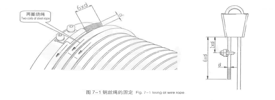
Fig. 7-1 wire rope fixing
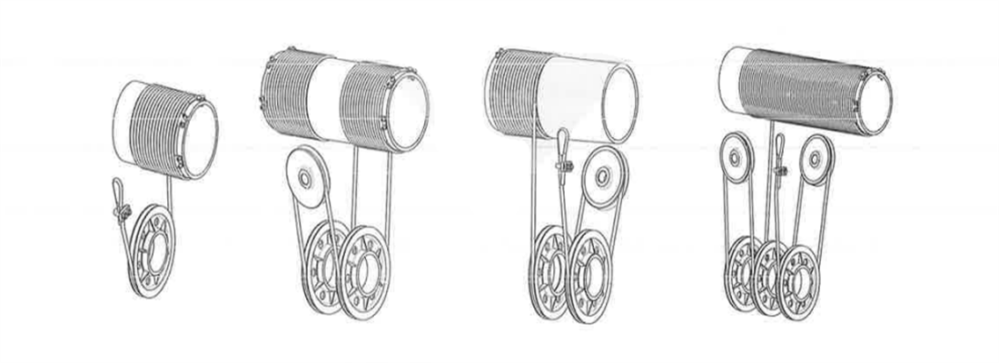
Fig. 7-2 wire rope winding diagram
A. Only wire ropes specified by the electric hoist manufacturer can be installed.
B. When uncoiling the steel wire rope, it should be prevented from tying or twisting.
C. When cutting the steel wire rope, measures should be taken to prevent the rope strands from spreading.
7.5 Lubrication
The lubrication of electric hoists is the key to ensuring the normal operation of equipment, extending service life, improving efficiency, and promoting safe production. The equipment must be lubricated and maintained regularly and carefully to check whether the lubrication system works normally.
| Table 7-2 Lubrication Table |
| Lubrication locations |
Refueling cycle |
Fule adding measures |
Recommended oil (grease) |
| Wire rope |
1 time/six months |
Daub |
oil (grease) for wire rope special |
| Lifting gear box |
1 time/three months |
Upper hole infusion |
Industrial gear HL-20 |
| Travelling gear box |
1 time/three months |
Upper hole infusion |
Industrial gear HL-20 |
| Table 7-3 Lubrication oil volume |
| Lifting capacity (t) |
Lifting gear box Oil injection volume(L) |
Travelling gear box Oil injection volume |
| 0.5 |
0.45 |
0.1 |
| 1 |
0.65 |
0.1 |
| 2 |
1.15 |
0.1 |
| 3 |
1.65 |
0.1 |
| 5 |
2.35 |
0.2 |
| 10~16 |
3.55 |
0.2 |
| 20~32 |
3.55 |
0.2 |
8.Fault analysis and troubleshooting
| Common faults |
main reason |
Troubleshooting |
| The motor starts reluctantly and makes a loud noise, unable to lift the load |
1. The power supply voltage is too low;
2. The brake is not safely disengaged;
3. Overload. |
1. Adjust the power supply voltage;
2. Adjust the brake clearance;
3. Load limiting |
| The electric hoist runs continuously in one direction |
1. Button stuck;
2. Contactor contact bonding |
1. Repair button;
2. Repair or replace the contactor |
| The gourd shell is live or there is abnormal noise from the running motor |
1. The I-beam is not grounded;
2. There is insulation damage to the motor or electrical device. |
1. The I-beam is not grounded;
2. There is insulation damage to the motor or electrical device. |
| Contactor contact burnt out or transformer burnt out |
1. The power on voltage is too high or too low;
2. The ambient temperature is too high and the humidity is too high |
1. Ensure voltage stability;
2. Ensure that the temperature and humidity meet the usage environment. |
| Braking failure or excessive braking distance |
1. Excessive brake clearance;
2. Oil stains on the braking surface;
3. Loose brake ring;
4. Pressure spring fatigue:
5. Poor contact between the brake ring and the conical surface of the rear end cover;
6. The coupling does not move properly or is stuck. |
1. Adjust the clearance according to 4.3.1;
2. Remove and clean the oil stains;
3. Replace the brake ring;
4. Replace the spring;
5. Dismantling and grinding;
6. Check its connection part |
| The temperature rise of the motor exceeds the upper limit of the nameplate |
1. Brake clearance too small:
2. Homework is too frequent;
3. Overload. |
1. Adjust the clearance;
2. Reduce the frequency of homework;
3. Load limiting. |
| The reducer has significant abnormal noise |
1. Poor lubrication;2. Damaged components such as gears and bearings; |
1. Add lubricating oil;
2. Replace damaged components. |
| Reducer oil leakage |
1. Poor or damaged sealing assembly between the box and the box cover.
2. Excessive refueling. |
1. Check or replace the oil seal;
2. Drain excess grease. |
| The steel wire rope is out of groove or tangled, and the rope guide is damaged |
Side pulling and inclined lifting |
Follow safety regulations for operation |
| Car wheel slipping |
Oil stains and other coverings on the I-beam track or wheel tread |
Remove the cover and sprinkle sand if necessary. |
| When starting and running, the body shakes and runs poorly |
Improper clearance between the side of the I-beam lower flange and the inner side of the wheel flange. |
Adjust the number of washers to maintain a reasonable gap. |
| The limiter is malfunctioning or the limit position is not appropriate. |
1. The stop block on the limit lever is loose or improperly positioned.
2. Power supply error |
1. Adjust and tighten the stop block;
2. Adjust the power supply. |
A. Before handling any faults, the power supply must be cut off.
B. When disassembling the explosion-proof hoist, the explosion-proof surface should be protected to prevent collision. When the explosion-proof shell is cracked, breathable, or the explosion-proof surface is damaged, it is scrapped.
C. According to the above table, if the fault cannot be determined and eliminated, please contact the manufacturer. The use of defective electric hoists can cause serious damage to equipment or personal injury!
9. Attached Drawing

.png)
.png)