
.WEBP) A truss manipulator is a fully automatic industrial equipment that is built on the basis of a right angle X, Y, Z coordinate system to adjust the workstation or achieve functions such as trajectory movement of the work piece. Its control core is achieved through industrial controllers (such as PLC, motion control, micro controller, etc.). By analyzing and processing various input signals (such as sensors and buttons) through the controller, making certain logical judgments, and issuing execution commands to various output components (relays, motor drivers, indicator lights, etc.), the joint movement between the X, Y, and Z axes is completed, thereby achieving a complete set of fully automatic operation processes.
A truss manipulator is a fully automatic industrial equipment that is built on the basis of a right angle X, Y, Z coordinate system to adjust the workstation or achieve functions such as trajectory movement of the work piece. Its control core is achieved through industrial controllers (such as PLC, motion control, micro controller, etc.). By analyzing and processing various input signals (such as sensors and buttons) through the controller, making certain logical judgments, and issuing execution commands to various output components (relays, motor drivers, indicator lights, etc.), the joint movement between the X, Y, and Z axes is completed, thereby achieving a complete set of fully automatic operation processes.
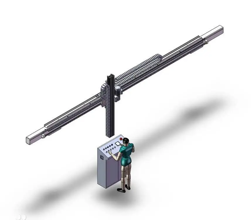
| 2.1 | The truss manipulator It is mainly composed of structural components such as columns, which are used to lift each axis to a certain height. It is mostly composed of welded components such as aluminum profiles or square tubes, rectangular tubes, and circular tubes. |
|
| 2.2 | The X-axis component, Y-axis component, and Z-axis component They are the core components of the truss manipulator, and their definition rules follow the Cartesian coordinate system. Each shaft component usually consists of five parts: structural components, guide components, transmission components, sensor detection components, and mechanical limit components. |
|
| (1) | Structural components | |
| Are usually composed of aluminum profiles or square tubes, rectangular tubes, channel steels, I-beams, and other structures. Their function is to serve as the installation base for components such as guide and transmission components, and also to be the main carrier of mechanical arm loads. | ||
| (2) | Guiding components | |
| Commonly include linear guide rails, V-shaped roller guide rails, U-shaped roller guide rails, square guide rails, and dovetail grooves. Their specific application depends on the actual operating conditions and positioning accuracy. | ||
| (3) | Transmission components | |
| Typically come in three types: electric, pneumatic, and hydraulic. Among them, electric components include gear and rack structures, ball screw structures, synchronous belt drives, traditional chain drives, and wire rope drives. | ||
| (4) | Sensor detection components | |
| Usually use travel switches as electrical limit switches at both ends. When the moving component moves to the limit switches at both ends, the mechanism needs to be locked to prevent it from exceeding the limit; In addition, there are origin sensors and position feedback sensors. | ||
| (5) | Mechanical limit group | |
| Serves as a rigid limit beyond the electric limit stroke, commonly known as a dead limit. | ||
| 2.3 | Jig and fixture There are different forms depending on the shape, size, material, etc. of the work piece, such as vacuum suction cup suction, chuck clamping, pallet or needle type fixture insertion, etc |
|
| 2.4 | The control cabinet which functions as truss manipulator’s brain, through industrial controllers, Collect input signals from various sensors or buttons, To send instructions to an executing element to execute according to a predetermined action. |
|

| ♦ | Efficient | its axes run in a straight line at extremely high speeds, and can be quickly responded to by servo motors; |
| ♦ | Stable | minimal repeatability error, up to 0.05mm; |
| ♦ | High intensity | 7x24 hours of work, no need to eat, sleep, etc; |
| ♦ | High precision | positioning accuracy can reach 0.02m m (due to production cost reasons, positioning accuracy can be appropriately enlarged according to usage conditions); |
| ♦ | High cost-effectiveness | Compared to articulated robots, they have a larger load weight and lower production costs, making them suitable for the basic national conditions of "China's intelligent manufacturing"; |
| ♦ | Easy to operate | based on the Cartesian coordinate system, its motion parameters are relatively simple. |
| 1. | Smart scan and three-dimensional imaging and remember the scanning results; | ||
| 2. | Follow system's instruction, Truss Manipulator adjusts posture automatically, intelligently plan path; | ||
| 3. | Based on the system's 3D scanning positioning, accurately grasp workpieces; (Robot manipulator has an anti loosening design) |
||
| 4. | Truss manipulator automatically plan paths and accurately feeds idle machines; (can avoid obstacles intelligently during the traveling) |
||
| 5. | According to system instructions, Automatically go to the station where the processing has been finished; | ||
| 6. | Accurately remove finished workpieces; | ||
| 7. | And based on the memory of 3D scanning results, Intelligently stack the finished workpieces. | ||